118 EM-ABS-01 for ACU 03/12
9 List of parameters
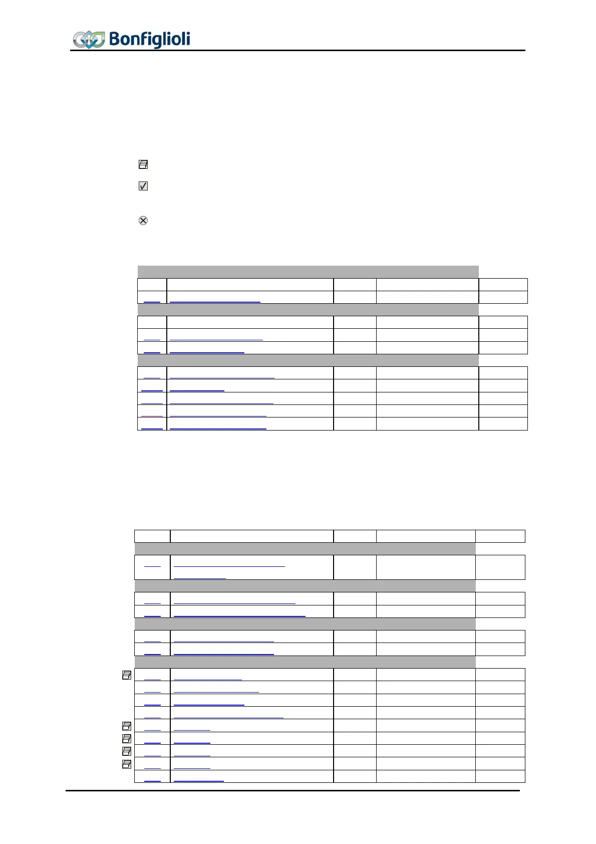
The parameter list is structured according to the menu branches of the control unit. For
better clarity, the parameters have been marked with pictograms:
The parameter is available in the four data sets.
The parameter value is adjusted by the SETUP routine if a control method for a
synchronous machine is selected for parameter
Configuration 30.
This parameter cannot be written when the frequency inverter is in operation.
9.1 Actual value menu (VAL)
Frequency inverter data
No. Description Unit Display range Chapter
016 EM Software version
10.2
Actual values of machine
No. Description Unit Display range Chapter
219 Encoder 2 Frequency Hz 0,0 ... 999,99
8.6
220 Encoder 2 Speed rpm 0 ... 60000
8.6
Actual values of frequency inverter
253
Analog Input EM-S1INA V -10 ... +10
8.6
1108
Act. Position u
Long
8.6.2
1267
Abs. Encoder Raw Data -
String
8.6.1
1273 Warning Dig. Encoder - Word
8.4.14
1274
Warning Dig. Encoder -
Selection
8.4.14
Note:
Parameter
Warning Dig. Encoder 1273 is intended for read-out via a PLC, parameter
Warning Dig. Encoder 1274 provides a brief description of the information in VPlus
and the keypad KP500.
9.2 Parameter menu (PARA)
No. Description Unit Setting range Chapter
Repetition frequency output
509 Repetition frequency EM-
S1/S2OUTD
- Selection
8.2.3
Digital outputs
513 EC2 Gear Factor Numerator - -300,00 ... 300,00
8.4.11
514 EC2 Gear Factor Denominator
- 0,01 ...300,00
8.4.11
Digital outputs
533 Op. Mode EM-S1OUTD - Selection
8.2.2
534 Op. Mode EM-S2OUTD - Selection
8.2.2
Analog input
560
Tolerance band % 0,00 ... 25,00
8.1.5
561 Filter time constant - Selection
8.1.8
562 Operation Mode - Selection
8.1.3
563 Error/Warning Behaviour - Selection
8.1.6
564
Point X1 % -100,00 ... 100,00
8.1.2
565
Point Y1 % -100,00 ... 100,00
8.1.2
566
Point X2 % -100,00 ... 100,00
8.1.2
567
Point Y2 % -100,00 ... 100,00
8.1.2
568 Adjustment - Selection
8.1.7

 Loading...

