03/12 EM-ABS-01 for ACU 111
Parameters Settings
No. Description Min. Max. Factory set-
ting
1115 Feed constant 1 u/U 2
31
-1 u/U 65536 u/U
1116
Gear Box: Driving Shaft Revolu-
tions
1 65 535 1
1117 Gear Box: Motor Shaft Revolutions 1 65 535 1
For application encoders, a
ear transmission between the application encoder and
motor must be parameterized via a gear factor (see chapter
8.4.11 “Gear factor speed
sensor 2”).
he conversions between the different reference systems are done automatically, the
user sets the target values in user units referred to the distance.
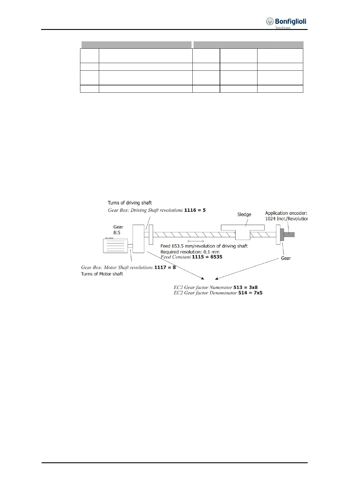
8.4.13.1 Example
For parameterization of a linear slide, the following properties are known:
Motor gear ratio: 8:5
pplication encoder
ear ratio: 7:3
Feed rate of linear axis: 635.5 mm/revolution of the output shaft
This results in the following parameterization:
eed constant 1115 = 6535 rev
Gear shaft turns 1116 = 5
Gear motor turns 1117 = 8
C2 Gear Factor Numerato
513 = 24
C2 Gear Factor Denominato
514 = 35
In order to move by 1 mm, a positioning order of 10 u must be executed.
Note: In the case of linear systems, the feed constant is typically specified in
the data sheet. If this value is unknown, it must be determined empirical-
ly. For empirical determination of the feed constant, refer to application
manual “Positioning”.

 Loading...

