03/12 EM-ABS-01 for ACU 21
5.3.2 Control terminals
The control and software functionality can be configured as required to ensure a reli-
able and economical operation.
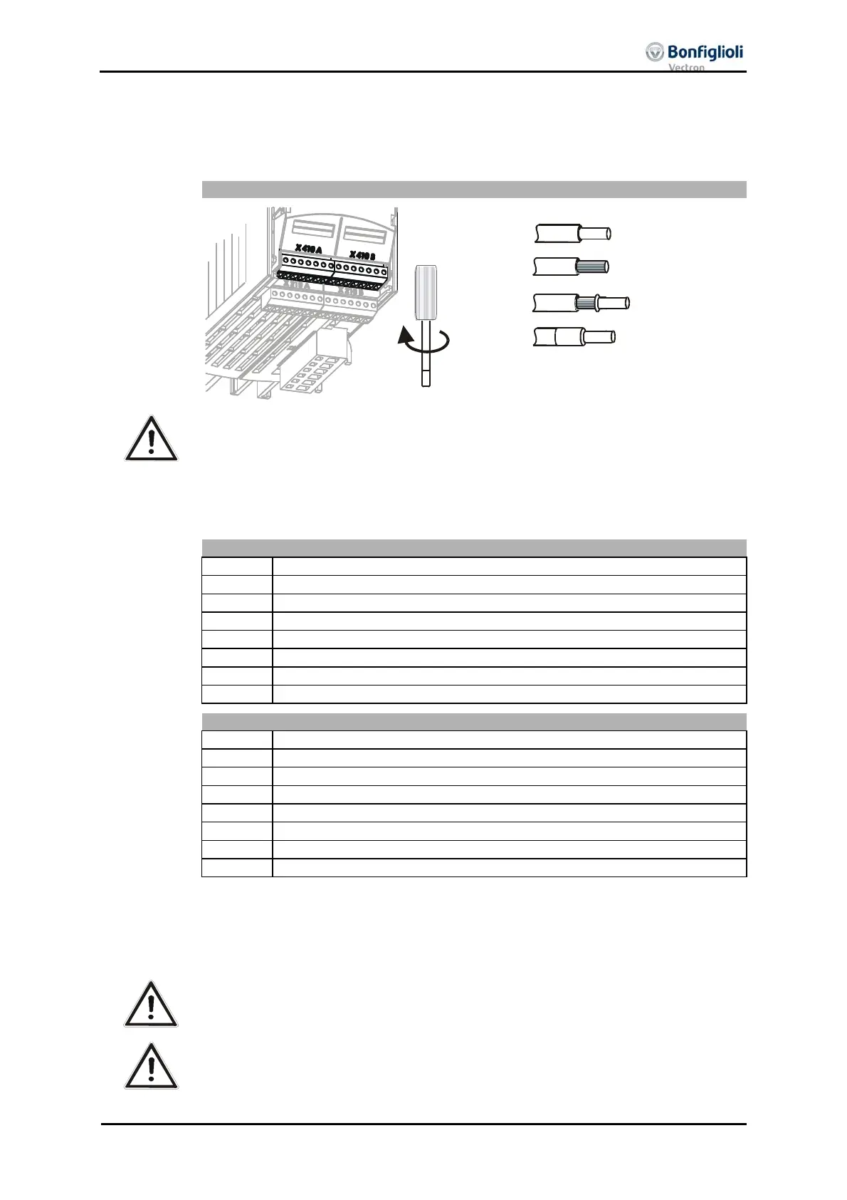
Extension module EM-ABS-01
0.14 … 1.5 mm
AWG 30 … 16
2
Wieland DST85 / RM3,5
0.14 … 1.5 mm
AWG 30 … 16
2
0.25 … 1.0 mm
AWG 22 … 18
2
0.25 … 0.75 mm
AWG 22 … 20
2
0.2 … 0.3 Nm
1.8 … 2.7 lb-in
Caution! Switch off power supply before connectin
or disconnectin
the control
inputs and outputs.
Atten-
tion!
In order to minimize electroma
netic interference and to obtain a
ood
si
nal quality, the shield of the cable is to be connected to
round on a
plane at both ends.
Control terminal X410A
Terminal Description
1 DC 24 V voltage input
2 Ground (GND) DC 24 V
3 Digital output EM-S1OUTD
1)
4 Digital output EM-S21OUTD
1)
5 DC 5 … 12 V voltage output
2)
6 Analog input EM-S1INA
1)
7 Ground DC 10 V
Control terminal X410B
Terminal Description
1 Ground (GND)
2 Digital input EM-S1IND
1)
3 Digital input EM-S2IND
1)
4 Digital input EM-S3IND
1)
5 System bus, CAN low
6 System bus, CAN high
7 Ground (GND)
1)
The control electronics parameters can be configured as required.
2)
The max. power available is reduced by the other used control outputs of the frequency
inverter and extension module. For sufficient power, connect an external power source to
the DC 24 V voltage input.
The voltage value can be adjusted via parameter
Supply voltage 1187.
Caution! The input for external DC 24 V voltage supply can withstand external vol-
tage up to DC 30 V. Avoid higher voltage levels. Higher voltages may de-
stroy the module.
Caution! The power output on terminal X410A.1 may be loaded with a maximum
power of 2 W. Higher power levels can damage components of the mod-
ule.

 Loading...

