116 EM-ABS-01 for ACU 03/12
8.7 Status of digital signals
The status of the digital signals can be read (decimal coding) via parameter
igita
inputs
250, Digital inputs (hardware) 243 and Digital outputs 254 . The display o
the digital input signals enables checking of the various control signals and their as-
signment to the corresponding software functions, in particular during commissioning.
fter conversion of the decimal fi
ure into the binary system, the bits 8, 9 and 10
dis-play the statuses of the inputs EM-S1IND, EM-S2IND and EM-S3IND.
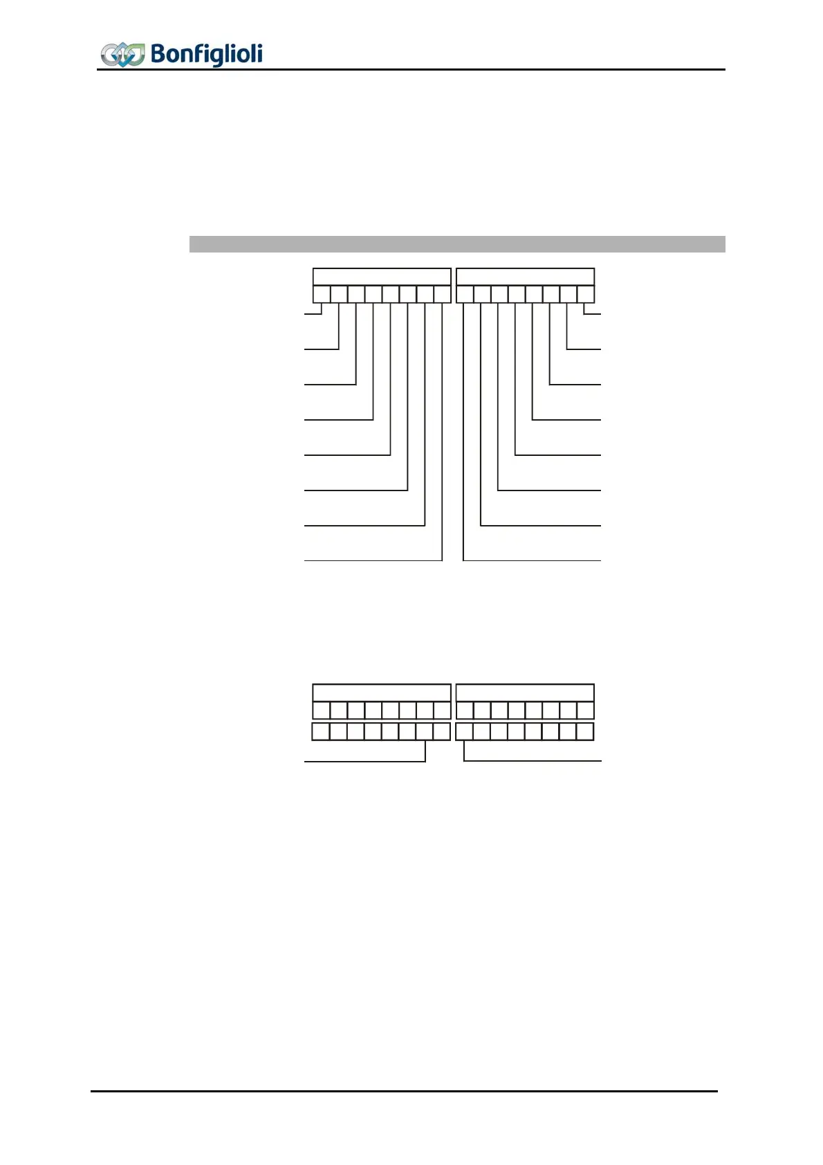
Coding of the status of the digital signals
8
7
6
5 4
3
2
0
Bit
15
14
13
12 11
10
9
Bit
Steuersignal 2
(Dezimalwert 2)
1
Steuersignal 1
(Dezimalwert 1)
Steuersignal 3
(Dezimalwert 4)
Steuersignal 5
(Dezimalwert 16)
Steuersignal 4
(Dezimalwert 8)
Steuersignal 6
(Dezimalwert 32)
Steuersignal 7
(Dezimalwert 64)
Steuersignal 8
(Dezimalwert 128)
Steuersignal 15
(Dezimalwert 16384)
Steuersignal 16
(Dezimalwert 32768)
Steuersignal 14
(Dezimalwert 8192)
Steuersignal 12
(Dezimalwert 2048)
Steuersignal 13
(Dezimalwert 4096)
Steuersignal 11
(Dezimalwert 1024)
Steuersignal 10
(Dezimalwert 512)
Steuersignal 9
(Dezimalwert 256)
Example:
The actual value parameter
Digital inputs 250 displays the decimal value 640. Afte
conversion into the binary system, the following combination results:
1 0 0 0 0 0 0
BitBit
0
8
7
6
5 4
3
2
0151413
12 11
10
9
1
000000 01
Binärsystem:
Steuersignal 8
(Dezimalwert 128)
Steuersignal 10
(Dezimalwert 512)
The following status of the digital input signals of the extension module was displayed:
−
Digital input EM-S1IND = 1 – control signal 8
−
Digital input EM-S2IND = 0 – control signal 9
−
Digital input EM-S3IND = 1 – control signal 10

 Loading...

