03/12 EM-ABS-01 for ACU 89
8.1.5 Tolerance Band and Hysteresis
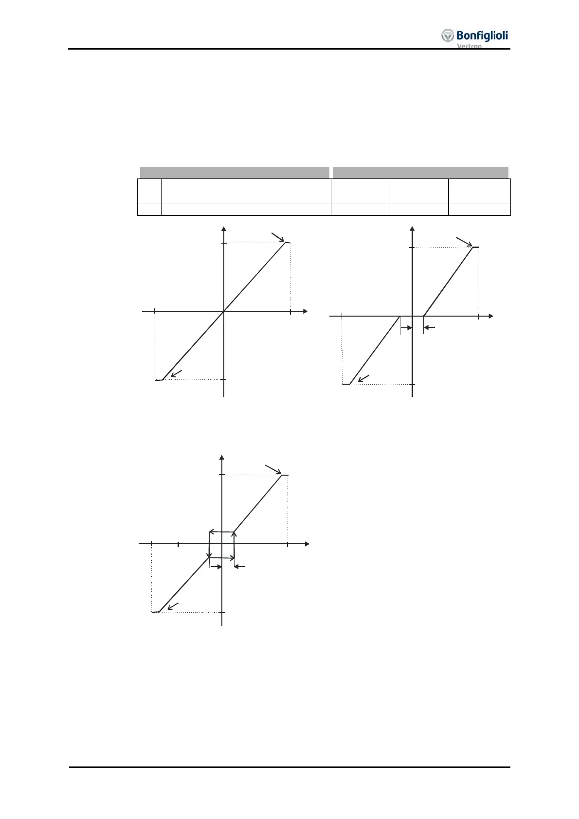
he analo
input characteristic with chan
e of si
n of the reference value can be
adapted by the parameter
Tolerance band 560 of the application. The tolerance band
to be defined extends the zero crossin
of the speed relative to the analo
control
signal. The parameter value (percent) is relative to the maximum current or volta
e
signal.
Parameters Settings
No. Description Min. Max. Factory set-
ting
560 Tolerance band 0,00% 25,00% 2,00%
(X1
Y1)
-10V
(-20mA)
+10V
(+20mA)
(
2
Y2)
pos. max. value
neg. max. value
Without tolerance band
(
1
Y1)
-10V
(-20mA)
+10V
(X2
Y2)
pos. max. value
Tolerance band
neg. max. value
With tolerance band
The default
Minimum Frequency 418 or Minimum Percentage 518 extends the pa-
rameterized tolerance band to the hysteresis.
(X1
Y1)
(X2
Y2)
pos. max. value
pos. min. value
neg. min. value
neg. max. value
Tolerance band
With tolerance band and minimum value
For example, the output variable comin
from positive input si
nals is kept on the
positive minimum value until the input si
nal becomes lower than the value for the
tolerance band in the negative direction. Then, the output variable follows the se
characteristic.

 Loading...

