DS7200V2-EXP | Installation Guide | 2. System Installation
and Setup
EN | 12
Bosch Security Systems, Inc. | 04/12 | F01U253045-02
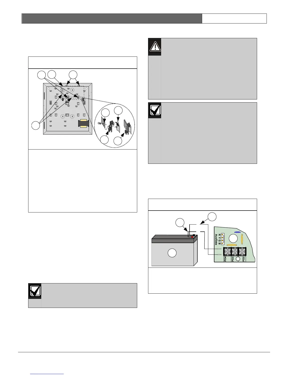
2.1.3 Control Panel Board Installation
1. Place the control panel board clips on the
appropriate standoffs in the enclosure. See
Figure 2.
Figure 2: Control Panel Board Mounting
1- Install support standoffs (0.08 mm) here
2- Control panel board location
3- Place edge of control panel board between
slots
4- Corner of control panel board
5- Control panel board clip
6- Enclosure standoff
7- Completed assembly
8- Control panel board terminal block
locations
Slide the control panel board into the slots at the
top of the enclosure, and then secure it with the
two screws provided. See Figure 2.
2.1.4 Ground and Transformer Connection
1. Connect the green/yellow earth ground wire
from the earth ground stud to the control
panel as shown in Figure 65 on page 129.
2. Connect the orange and yellow wires from
the transformer to the control panel as shown
in Figure 65 on page 129.
2.1.5 Mains Connection
Make sure you have a good earth
ground before completing the
following steps.
Follow all electrical codes when routing the AC
Mains power connection to the control panel.
2.1.6 Standby Battery Installation
High current arcs are possible. The
red (+) battery lead and the control
panel’s “BATT +” connector can
create high current arcs if shorted to
terminals or enclosure. Use caution
when working with the red lead and
the control panel’s “BATT +”. Always
disconnect the red lead from the
battery before removing the red lead
from the control panel.
Replace the standby battery every 3
to 5 years under normal use.
Exceeding the maximum output
ratings, or connecting the control
panel to an outlet that is routinely
switched off, causes heavy
discharges. Routine heavy
discharges can lead to premature
battery failure. Record the date of
installation directly on the battery.
When the standby battery and the transformer
connections are made, the control panel charges
the standby battery as you finish the installation.
See Figure 3 for details when installing the
standby battery.
Figure 3: Standby Battery Connections
1- Standby battery
2- Control panel board
3- Black (-) line
4- Red (+) line