DS7200V2-EXP | Installation Guide | 2. System Installation
and Setup
EN | 25
Bosch Security Systems, Inc. | 04/12 | F01U253045-02
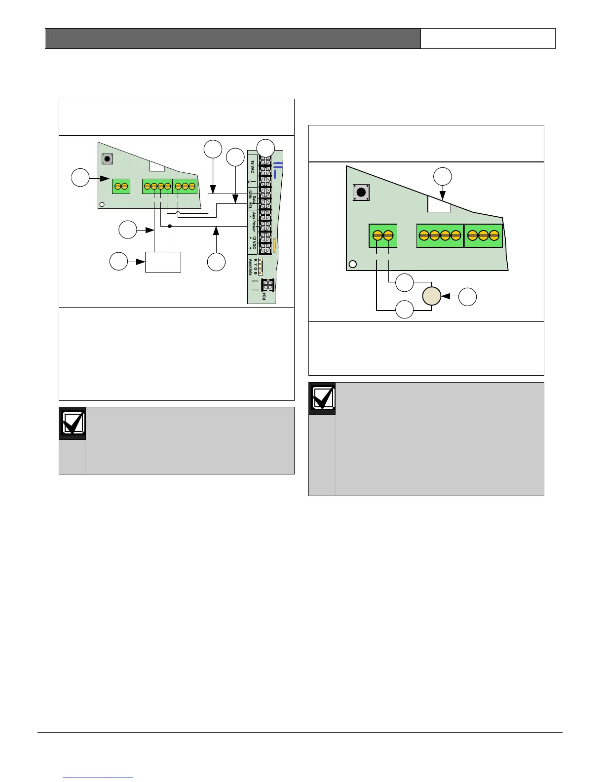
If you need to power the DX2010 with an external
12 VDC power supply, wire it as shown in Figure
30.
Figure 30: DX2010 to Control Panel
Wiring (External Power Supply)
1- DX2010 Module
2- Green (G) data wire
3- Yellow (Y) data wire
4- Black (-) wire
5- Red (+) wire
6- External 12 VDC power source
7-
Control panel board
Do not tie the black (-) output to
earth ground when using an external
power supply. A ground fault
condition is reported if black (-) is
grounded.
2.6.4 DX2010 Auxiliary Output Wiring
The DX2010 can provide 12 VDC at up to 100 mA
from the Auxiliary Output (-) OUT (+) terminals to
power external devices such as motion detectors.
See Figure 31.
Figure 31: DX2010 Auxiliary Output
Wiring
1- DX2010 Module
2- Motion detectors, photo beams, etc.
3- Black (-) wire
4- Red (+) wire
The following maximum wire lengths
apply when wiring the DX2010’s
auxiliary output to remotely powered
devices, such as PIRs and smoke
detectors:
− 15 m (49.2 ft) for 0.8 mm (#22
AWG) wire.
− 30 m (98.4 ft) for 1.2 mm (#18
AWG) wire.
BATT+
BATT-
2
3
4
7
+OUT- TMPR 1 COM
B
Y
G
5
(+)
(-)
R
6
1