DS7200V2-EXP | Installation Guide | 3. Control Panel
Programming
EN | 105
Bosch Security Systems, Inc. | 04/12 | F01U253045-02
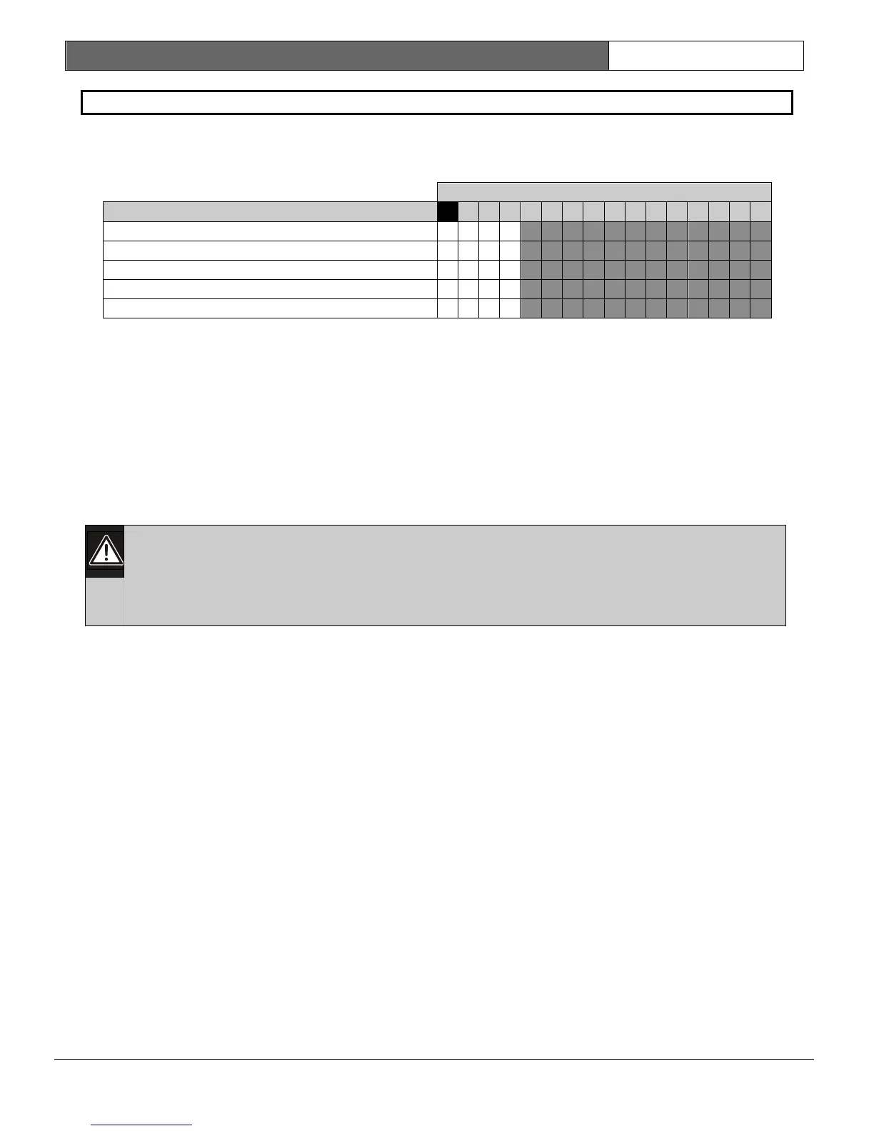
Network Interface Module Options
• Address: 3541
• Default: 0
• Selections: 0 to 3
Enter This Data Digit to Select Options
Network Interface Module Options
No Alternate Communication
Enable Alternate Communication
• Enable Alternate Communication: Select this option to supervise the connection between the
control panel and the network interface module (DX4020). The network interface module’s DIP
switch address must be set to 134. Do not select this option if there is no network interface
module connected to the system.
• Include IP Address: Select this option to use the IP address entered in IP Address 1 (2) for
Destination 1 (2) (see page 101) instead of the IP address stored in the DX4020 for network
communication. Select “Enable Alternate Communication” in Alternate Communication Options
(refer to page
102) for the appropriate IP address. Select this option when using a DX4020. Do
not select this option when using a DX4010i.
3.10 DACM Configuration
The control panel supports up to 8 DACMs. However, each DACM added to the system
replaces one keypad. If 8 DACMs are added, you cannot add a keypad. For full system
control, make sure at least one text keypad is included in the system.
For complete installation, programming, addressing, and operation instructions, see the
documentation supplied with the DACM.
Configuring a DACM into the control panel is a three-step process:
1. Using Table 30 on page 80, assign the DACM’s door contact as a location. For example, DACM
#1’s door contact will be assigned to Location #5.
a. Enter “6” at Address 0726 for the device type.
b. Assign a zone function and enter it in Address 0727.
c. Assign an area to the DACM in Address 0728. Each DACM’s door contact can only use
one location.
d. Repeat the area assignment in Keypad #/Door Access Control Module (DACM) Area
Options. For example, if you selected Area 1 for Address 0728, then you must enter “9”
in Address 0679. This address is for Keypad/DACM #1. “9” identifies the device as a
DACM #1 in Area 1.
e. Assign a zone number in Addresses 0729-0730 if the zone number must be different
than the location number.
2. Enter the location number in DACM Location Assignment. For this example, enter “0” in
Address 3546, and “5” in Address 03547. This assigns the control panel’s Location #5 to
DACM #1.
3. Assign global options in Address 3562 (see DACM Global Options on page 107). The entry you
make here affects all DACMs connected to the control panel.
 Loading...


