152 en | Technical Data Modular Fire Panel
09.2017 | 11.3 | F.01U.028.089 System Information Bosch Sicherheitssysteme GmbH
Installation of the power supply unit is described in CZM0004A 4Zone Conventional Module,
page 107.
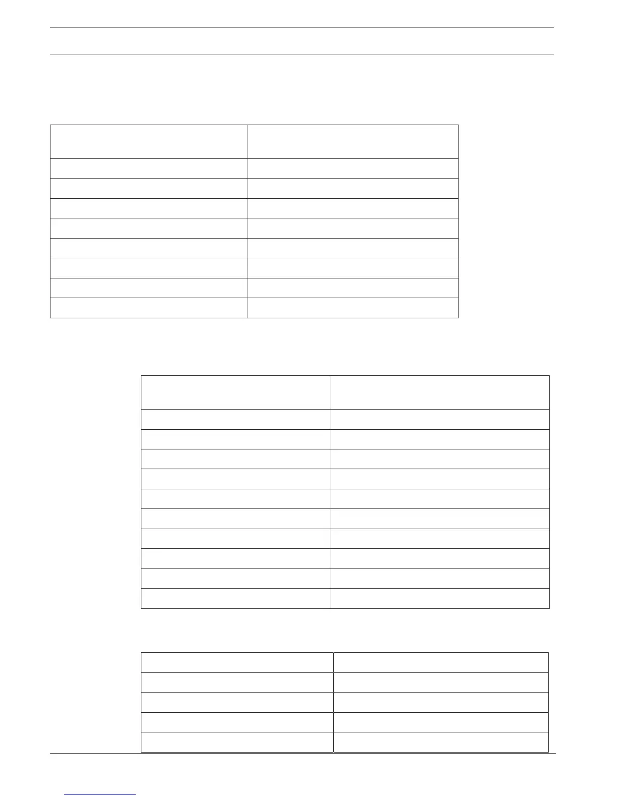
7.5.4 ENO0000B Fire Service Interface Module
Operating and display elements 2 LEDs (1x red, 1x yellow)/1 button (LED
test)
Input voltage 20VDC to 30VDC
Current consumption
– In standby 25mA
– All relays tripped 60mA
– Key deposit heating additional 240mA
Permissible relay contact load 1A/30V
Space required (H x W x D) approx. 127 x 96 x 60mm
Weight approx. 150g
Installation of the power supply unit is described in ENO0000B Fire Service Interface Module,
page 107.
7.5.5 FPE‑5000‑UGM Interface Module
Operating and display elements 4 two color LEDs (green = transmission / yellow
= fault), 1 button (LED test)
Input voltage 20VDC to 30VDC/5VDC ± 5%
Maximum cable length 1000m
Maximum line resistance 70Ω
Transmission rate 9600bit/s at 1000m to 38400bit/s at 200m
Maximum current consumption
– Standby operation 7mA (at 24V)
– One transmission path active 10mA (at 24V)
– Both transmission paths active 13mA (at 24V)
Space required (H x W x D) approx. 110 x 90 x 60mm
Weight approx. 150g
Installation of the power supply unit is described in FPE‑5000‑UGM Interface Module, page 109.
7.5.6 IOP0008A Input/Output Module
Input voltage 20VDC to 30VDC/5VDC ± 5%
Maximum current consumption 15mA at 24VDC
Maximum switch-on current 700mA (short-circuit protected, I
max
= 1.5A)
Maximum cable length 3m
Space required (H x W x D) approx. 127 x 96 x 60mm

 Loading...


