Modular Fire Panel Product Description | en 13
Bosch Sicherheitssysteme GmbH System Information 09.2017 | 11.3 | F.01U.028.089
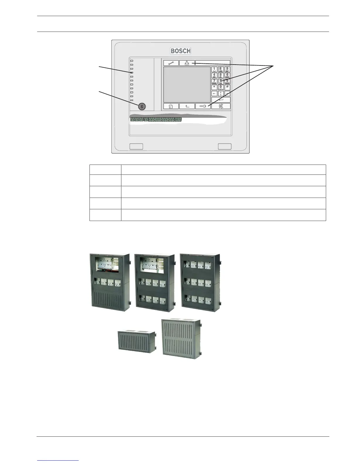
Figure2.4: FMR-5000-C Remote Keypad
Position Description
1 Touch screen
2 Membrane keys
3 LEDs for displaying the operating status
4 Key switch
Information on installing the Remote Keypad can be found in Remote Keypad, page 127.
The technical data can be found in Remote Keypad, page 149.
2.4 Housings for Frame Installation
Figure2.5: Housings for frame installation
Frame installation housings are always used in conjunction with the associated mounting
frame.
The housings are hooked into the mounting frame and can be swiveled to the front for
installation and servicing. The mounting frames are screwed to the wall surface and hold the
pre-cabling.
Alternatively to surface mounting, installation in 482.6mm (19") racks is also possible using
special installation kits.
12V/45Ah batteries can be used in the frame installation housing.

 Loading...


