Modular Fire Panel Installation | en 123
Bosch Sicherheitssysteme GmbH System Information 09.2017 | 11.3 | F.01U.028.089
You can find the installation instructions for the FPP‑5000‑TImodule at
www.boschsecurity.com (document number for installation instructions: F.01U.081.396).
The technical data can be found in FPP‑5000‑TITrouble Interface, page 157.
FPP-5000-TI13 Communication Interface
The Communication Interface is an extension for the External Power Supply Unit Kit only. It is
the communication interface between the External Power Supply Unit Kit and the panel, and
transmits the following faults to the panel:
– Mains fault
– Battery fault
– Battery internal resistance fault
– BCM Battery Controller Module fault
– Short 24 V outputs
– Ground fault
Additionally, with the programming software, the switching outputs can be programmed and
the settings for the line monitoring according to EN54-13 can be done.
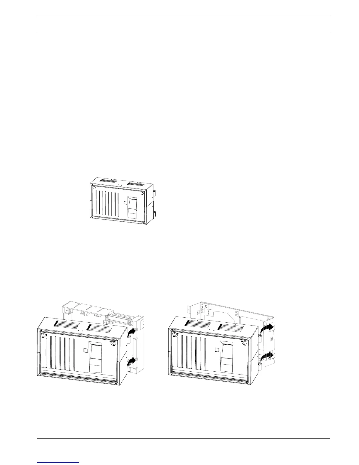
4.13 THP2020A Thermal Printer
Figure4.78: THP2020A Thermal Printer
Scope of Delivery
– Sheet steel housing, painted
– Thermal printer (installed), with connection cable
– Plastic front panel
– Accessories pack with installation materials
Required for Installation
– FSH0000A Mounting Frame Small, or
– FRS0019A Rack Installation Kit, Small
Figure4.79: THP2020A mounting frame/installation kit
General Information
– The following information can be sent to the printer:
– Operating procedures on the panel (e.g. daytime operation)
– Alarm and fault messages
– Plain text; programming is carried out via the programming software FSP-5000-RPS.

 Loading...


