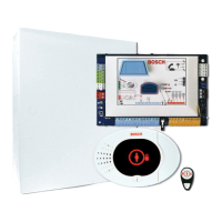
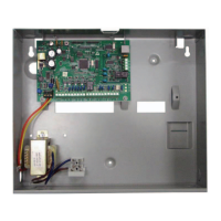
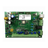
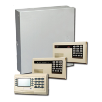
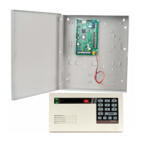
Part Description
EZPS-FRA Power supply for motion detectors and sirens
IPP-PSU-2A5 Supervised auxiliary power supply
ICP-EZVM-FRF Voice module in French
DX2010 8 wire zones expansion board
Siren Wiring in a NF A2P Certified Installation
Use only sirens with a backup battery. Sirens which require a primary voltage of 14.4 V can be
powered by the optional module EZPS-FRA, or the auxiliary power supply IPP-PSU-2A5.
Bring the hold-on +12 V through panel PO1, set it as the interior siren, as shown on the siren
installation guide. Depending on the current requirement of the siren battery, the hold-on +
voltage can be taken from the orange terminal, white terminal, +14.4 V of the siren power
output of optional board EZPS-FRA, or one of the outputs of auxiliary power supply IPP-
PSU-2A5.
Notice!
In an NF A2P certified installation, do not use the same power supply for both the siren and
the motion detectors.
Motion detector wiring in an NF A2P certified installation
Power for motion detectors shall be separated from power for sirens. Power for motion
detectors can either come from the white terminal + and -, or by the optional board EZPS-FRA
when the number of motion detector requires separate power lines, or by the auxiliary power
supply IPP-PSU-2A5.
Control panel configuration in an NF A2P certified installation
Check that each parameter is in the range of authorized values for NF A2P certified
installations.
Current chart in an NF A2P Type 2 certified installation
To meet the 36 hours of backup power, check that the current required by all the equipments
used in the system is lower than the backup current available:
– Max current in idle state: 465 mA (i.e. 270 mA of current for the control panel , with one
control center)
– Max current in alarm: 1000 mA (i.e. 675 mA of current for the control panel, with one
control center)
Refer to the chart below.
Max Current in Idle State Max Current In Alarm State
Module I Max Total I Max Total
Easy Series control panel 85 mA x1 85 mA 160 mA x1 160 mA
Current for the control panel: A ....mA ...mA
IUI-EZ1-NEW control center (at
least 1)
110 mA x Qty 165 mA xQty
Current on the option bus: B ....mA ....mA
Motion detector(s) x Qty x Qty
Siren(s) x Qty x Qty
Easy Series Control Panel Agency Approvals and Requirements | en 13
Bosch Security Systems, Inc. System Reference Guide 2014.09 | 01 | F.01U.306.221
 Loading...
