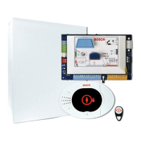
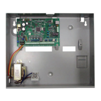
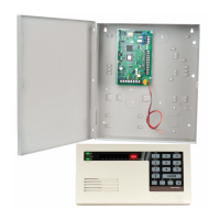
System Components and Wiring
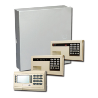
This section provides an overview of the system components, wiring, and placement in the
enclosure.
Callout Description
1 Control Center Mount within 3 m of control panel, Use
CAT5 cable (twisted pair) for audio
bus, Set data bus address (1 - 4), up to
4 controls max
2 RADION receiver
1 = Normal Operation
5 = Maintenance Mode
3 DX2010 Point
Expander
Data bus Adr 102: Points 9-16
Data bus Adr 103: Points 17-24
Data Bus Adr 104: Points 25-32
2.2
18 en | Overview Easy Series Control Panel
2014.09 | 01 | F.01U.306.221 System Reference Guide Bosch Security Systems, Inc.
 Loading...
