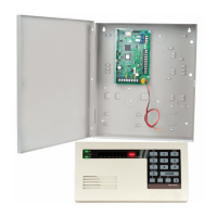
Intrusion Point Wiring
You can wire Supervised Points 1 to 32 as wired or wireless intrusion points.
To program Supervised Points 1 to 32 as intrusion points, refer to Points, page 44.
See also
– Points, page 44
– Outputs, page 46
– Points, page 44
Apply System Power
Notice!
Because the control panel is permanently connected equipment, a readily accessible
disconnect device must be included into the building installation wiring.
An external earth ground is required to ensure safe and proper system operation. Failure to
ground the system can cause personal injury and degraded system performance, such as
problems with tokens or noise on the control center.
Connect battery power to the control panel. Refer to System Components and Wiring, page 18.
Use a cable tie to secure the incoming AC wires to the enclosure, where required.
Initial System Startup
1. Apply AC power to the system.
2. Refer to the table below for the Initial System Startup sequence.
Stage Time Interval Control Center RADION receiver
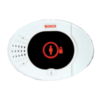
1 0 to15 sec Intermittent flashing green icon LED on continuous
slow flash: 1 second
on, 1 second off.
Indicates the receiver is
being programmed with
the zone and
transmitter ID’s from
the compatible control
panel.
2 15 to 45 sec Flashing amber circle
3 45 to 75 sec Single rotating amber segment
4 75 sec Solid green circle
Table 3.2: Initial System Startup Sequence (No RADION devices discovered)
Configure the System
Upgrade the Control Panel (Optional)
Insert the ICP-EZRU-V4 ROM update key.
3.3
3.4
3.5
3.5.1
32 en | System Installation and Configuration Easy Series Control Panel
2014.09 | 01 | F.01U.306.221 System Reference Guide Bosch Security Systems, Inc.
 Loading...
