Installation considerations
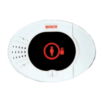
Use the provided anchors and screws to mount the repeater in locations accessible for future
maintenance. Mount the repeater onto a wall.
Notice!
Mount the repeater in a location removed from metal. Metal objects (duct work, wire mesh
screens, boxes) reduce RF range
Wiring considerations
Notice!
Do not install long cable runs next to high-current power feeds. Keep cable lengths as short
as possible to minimize noise pickup.
Ensure that the wiring used meets the following specifications:
– Two-conductor unshielded wire.
– The minimal requirement for wire length is 1.83 m (6 ft) from the repeater
Specifications
Dimensions 139.70 mm x 209.60 mm x 31.80 mm
(5.50 in x 8.25 in x 1.25 in)
Power/Voltage
(Standby battery)
16.5 VAC, 40VA (~)
(EN voltage range: 16.5 VAC– 18 VAC) AC Type (device)
Rated 3.7 VDC, 3050mAH EVE ENERGY CO Part No P0046-LF (Not user
replaceable). For standby battery to be operative, the tamper switch is
required to be engaged.
Power source type: A
Low battery level: 3.5V
Transformer power/voltage Must meet country specific requirements
Current Draw 60 mA
Wire Gauge 0.65 mm (22 AWG) to 2.0 mm (18 AWG)
Temperature (operating) Functional range: -10゚C to +49゚(+14゚F to +120゚F)
EN 50130-5 Class II only: -10゚C to 40゚C (+14゚F to +104゚F)
Relative Humidity 0% to 93% (non-condensing)
Device testing To ensure proper functionality, the device must be tested at least once
every year by an installer.
Wall and Cover Tamper Switch Transmits a tamper signal when someone removes the device from its
base or pulls it away from the wall.
Frequency 433.42 MHz
Table 8.4: Specifications
8.6.1
8.6.2
8.6.3
76 en | Device Specifications and Overview Easy Series Control Panel
2014.09 | 01 | F.01U.306.221 System Reference Guide Bosch Security Systems, Inc.
 Loading...
