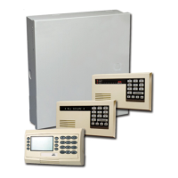
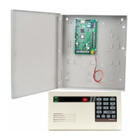
2. If you install more than one control center, each control center must have a unique
address. Valid addresses are 1 to 4. Refer to the figure below for the location of the
address switch.
Figure 3.1: Control Center Address Switch
1
Control Center’s front cover
2 Address switch’s default settings
1. Mount the control center base to the desired surface using the appropriate mounting
holes. Use the built-in level in the control center base as a guide.
Notice!
Mount the base to a non-metallic surface that is near the primary entry/exit door.
If you install more than one control center, ensure that there is at least 1.2 m between each
control center.
Avoid mounting the control center near existing phone lines.
Avoid mounting the control center near other electronic devices.
2. Connect the control center data bus terminals to the control panel data bus terminals.
Refer to System Components and Wiring, page 18.
3. Connect the control center audio bus terminals to the control panel audio bus terminals.
Twisted pair wiring is recommended for audio bus terminals. Refer to System Components
and Wiring, page 18.
4. Reconnect the control center and base, and then lock the control center.
Refer to Control Center, page 70 for an overview of the various control center display states.
Easy Series Control Panel System Installation and Configuration | en 27
Bosch Security Systems, Inc. System Reference Guide 2014.09 | 01 | F.01U.306.221
 Loading...
