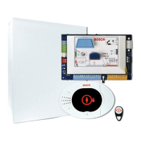
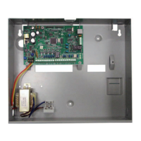
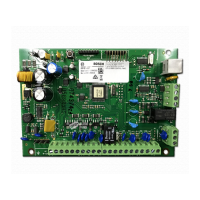
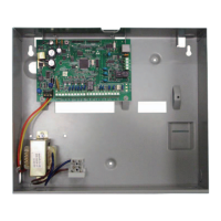
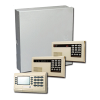
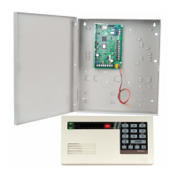
Figure 3.3: Mounting the module to the exterior wall of the enclosure
Callout ᅳ Description
1 ᅳ B450
2 ᅳ Enclosure (outside wall shown)
3 ᅳ Mounting screws (3 screws included)
Installing in a control panel enclosure
Install the B450 on the inside enclosure wall that also contains the supported control panel.
The control panel powers the B450 via the terminal block or bus connection.
Installing in a separate enclosure
Install the B450 on the inside wall of a separate enclosure. The control panel in a nearby,
separate enclosure powers the B450 via the terminal block or bus connection.
Installing in a separate enclosure with separate power supply
Install the B450 on the inside wall of a separate enclosure that also has a separate external
power supply such as the B520 Auxiliary Power Supply Module.
Installing and mounting the magnetic antenna:
1. Place the magnetic antenna on top of the enclosure, or vertically on another metal
surface.
Notice!
If you are experiencing a weak signal, place the antenna on top of a metal surface that has a
radius of 10.16 cm (4 in) for optimal performance.
2. Route the antenna cable through a knock-out in the enclosure wall.
3. Connect the antenna cable to the module.
4. Secure the antenna cable to the inside of the enclosure.
5. Secure the extra antenna cable length inside the enclosure.
Easy Series Control Panel System Installation and Configuration | en 29
Bosch Security Systems, Inc. System Reference Guide 2014.09 | 01 | F.01U.306.221
 Loading...
