X7-8-Install-IG100 Installation Guide
Brocade
®
X7-8 Director Hardware Installation Guide
6. Airflow Label
7. Captive Screw
8. Power Cable Restraint Cover
Consider the following information when connecting AC power:
•
The X7-8 Director can have three or four power supplies installed, depending on the quantity ordered. You should
use the high-voltage line (200 to 277 VAC) because of better power conversion efficiency. See "Power Supply
Requirements" in the Brocade X7 Director Technical Specifications for minimum power supplies required for AC low
and high voltage line operation, redundancy in case of power supply failure, and other specifications.
•
Redundant AC primary power connections ensure high availability. Each power supply has its own connector. If four
power supplies are installed, four primary power connections are required for the X7-8 Director for optimum efficiency
and redundancy.
Power supplies can be removed and replaced without special tools. If you are replacing one power supply in a
configuration with N+1 or greater redundancy, the director can continue operating during the replacement if procedures
in this guide are followed. Otherwise, installed blades may power off. See "Power supply requirements" in Brocade X7
Director Technical Specifications for more information about power supply redundancy.
Power cords are available from Brocade. Power cords are 6m (19.68 ft.) long and contain three colored 14 AWG
unterminated wires, which are described in the following table:
Table 30: HVAC/HVDC Power Cable Wiring
Label (Color) Function
(black) Negative (-)
(green with yellow stripe) Earth ground (PE)
(red) Return positive (+)
Power cords have an Anderson Saf-D-Grid 400 connectors on the power supply end and unterminated wires on the other
end for attaching to AC or DC power sources. Either attach an AC power plug to these wires that meet your facility and
local code requirements or connect wires to appropriate DC power terminal blocks.
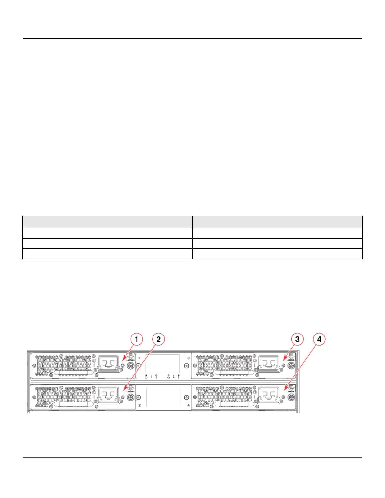
Power Supply Assembly Numbering
The following figure illustrates the location and number identification of power supply assemblies in the chassis.
Figure 53: HVAC/HVDC Power Supply Assembly Numbering
1. Power Supply 1
2. Power Supply 2
3. Power Supply 3
X7-8-Install-IG100
164