X7-8-Install-IG100 Installation Guide
Brocade
®
X7-8 Director Hardware Installation Guide
Port-Side Slot Numbering
The X7-8 Director contains 10 full-height slots and two half-height slots, for a total of 12 slots. Facing the port side of the
device, the half-height slots are on the left, numbered 1 (top slot) and 2 (bottom slot). The remaining full-height slots are
numbered 3 through 12, counting from left to right of chassis.
Slots contain guide pins and connectors designed for specific blade types. Only install the control processor (CP), core
routing (CR), port, and extension blades into slot numbers as follows:
•
Slots 1–2 are restricted to CP blades. Note that the blade installed in slot 1 will be designated as CP0, while the blade
in slot 2 will be designated as CP1 in CLI command and message output.
•
Slots 3–6 and slots 9–12 are restricted to port and extension blades.
•
Slots 7–8 are restricted to CR64-8 core blades.
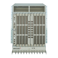
Nonport-Side View of the Device
The following figure shows the nonport-side view of the X7-8 Director with all fan and power supply assemblies installed.
X7-8-Install-IG100
17