X7-8-Install-IG100 Installation Guide
Brocade
®
X7-8 Director Hardware Installation Guide
•
See the "Power Supply Specifications (per PSU)" in the Brocade X7 Director Technical Specifications
for maximum output power, input voltage, input line frequency, and other specifications for your power supply
model.
•
See the "Power Supply Requirements" section in the Brocade X7 Director Technical Specifications for the
minimum number of power supplies required for operation and redundancy when different input voltages are
applied, such as low line and high line AC.
•
See the "Power Consumption" sections in the Brocade X7 Director Technical Specifications for power output
data and the minimum number of power supplies for supported input voltages.
•
Redundant primary power connections ensure high availability. Each power supply assembly has its own
connector, so the number of primary power connections is four for optimum efficiency and redundancy.
–
Two World Wide Name (WWN) cards located on the nonport side of the device behind the WWN card bezel.
–
Port blades use small form-factor pluggable (SFP+, QSFP+, and QSFP28) optical transceivers. For details on
supported transceivers per blade type, see Supported Transceivers and Cables.
–
Core routing blades use QSFP28 or QSFP56 optical transceivers. For a list of supported transceivers for these
blades, see Supported Transceivers and Cables.
•
Chassis door. This door must be installed to meet EMI compliance certification.
•
A cable management comb. These combs install on the chassis below the blades for cable management.
NOTE
Device control processors and management modules contain batteries for RTC/NVRAM backup. Do not attempt
to replace these batteries. Dispose of hardware components that contain these batteries as required by local
ordinances and regulations.
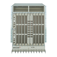
Port-Side View of the Device
The following figure shows the port-side view of the X7-8 Director with installed blades identified. Note that the SX6
extension blades is not shown in the following figure, but would install in the same slots as the FC32-X7-48 or FC64-64
port blades. A maximum of four SX6 blades are supported.
X7-8-Install-IG100
15