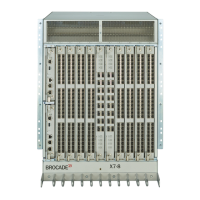
X7-8-Install-IG100 Installation Guide
Brocade
®
X7-8 Director Hardware Installation Guide
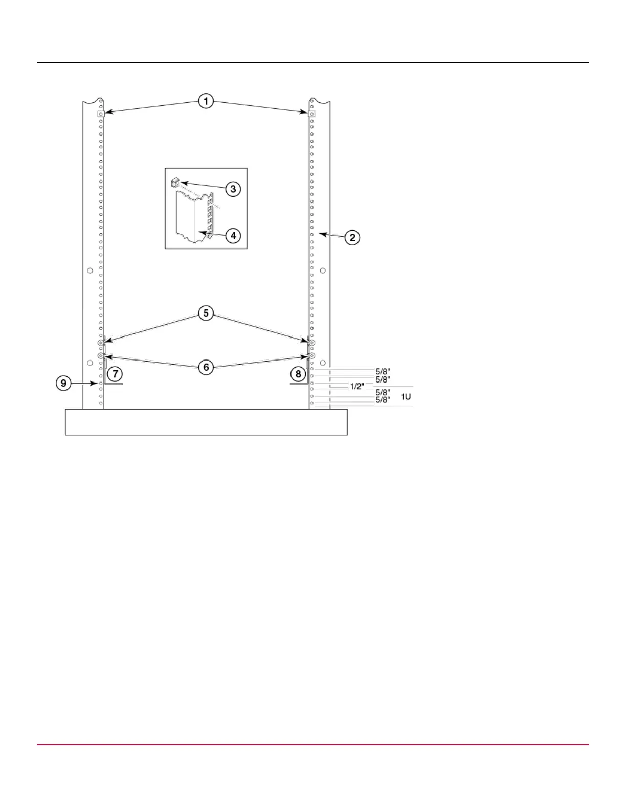
Figure 5: Nut and Screw Locations for Mounting the Device
1. 10-32 Clip Nuts (for round holes)
2. Rail
3. 10-32 Retainer Nut (for square holes)
4. Rail
5. Top Screws in Shelf Bracket
6. Bottom Screws in Shelf Bracket
7. Left Rack Mount Shelf Bracket
8. Right Rack Mount Shelf Bracket
9. Hole 1
NOTE
Standard EIA rails have holes in sets of three; spaces between the holes are 1.58 cm, 1.58 cm, and 1.27 cm
(5/8 in., 5/8 in., and 1/2 in).
4. Tighten the adjusting screws on the sliding portion of the rack mount shelf brackets to a torque of 37 cm-kg (32 in.-lb).
5. Attach the clip nuts (for rails with round holes) or retainer nuts (for rails with square holes) to the vertical rails on the
exhaust aisle side of the rack (see the previous figure). These clip nuts are used for securing the port side of the
X7-8-Install-IG100
31