TT100 In-Line Viscometer Installation, Operation, Maintenance and Service Instructions
P/N M/97-520 7-1
Section 7 - Troubleshooting
Introduction
The information in Section 7 will help you troubleshoot problems when
they occur. The problems presented in Table 7-1 are followed by possible
causes and corrective actions. The causes and corresponding actions are
listed in their order of probability of occurrence.
Technical Inquiries
Refer to Appendix A and call Brookfield Engineering Laboratories, Inc. if
you are in need of assistance.
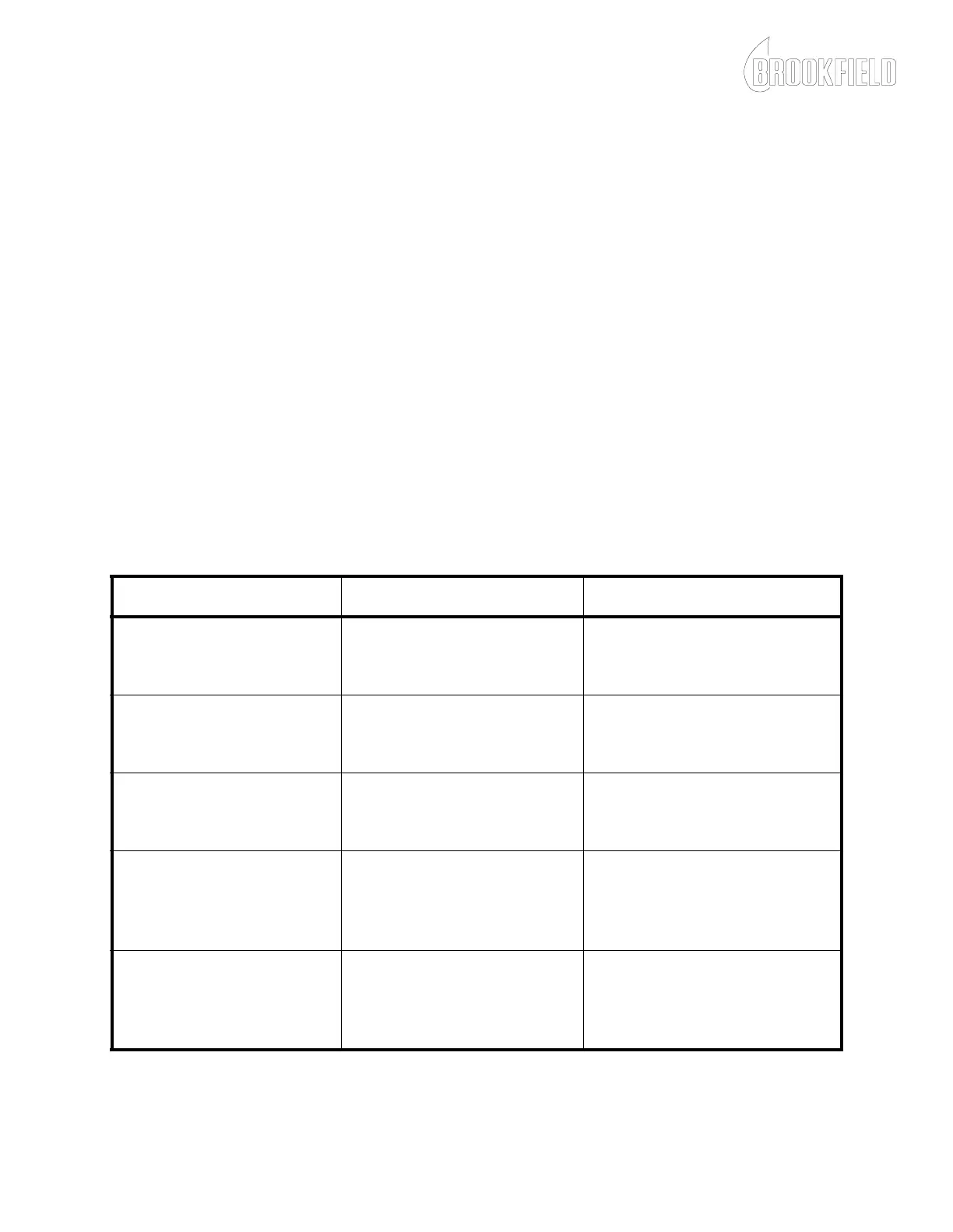
Table 7-1: Process Fluid Leaks
Problem Possible Cause Corrective Action
Leak between chamber and
sensing endcap.
Damaged O-ring Refer to Sensing Endcap
Service in Section 6 and
replace the O-ring.
Leak between sensing end-
cap and torsion element.
Damaged O-ring Refer to Sensing Endcap
Service in Section 6 and
replace the O-ring.
Leak at Microsyn housing Damaged torsion element Refer to Sensing Endcap
Service in Section 6 and
replace the torsion element.
Leak from drive shaft seal/
bearing housing of single
mechanical seal
viscometer
Damaged mechanical seals Refer to Mechanical Seal
Replacement in Section 6 and
replace the mechanical seals.
Leak from drive shaft seal/
bearing housing of double
seal mechanical seal
viscometer
Damaged O-ring or double
seal housing
Refer to Double Mechanical
Seal Assembly Replacement
in Section 6 and replace the
double seal assembly or O-ring.