TT100 In-Line Viscometer Installation, Operation, Maintenance and Service Instructions
P/N M/97-520 1-5
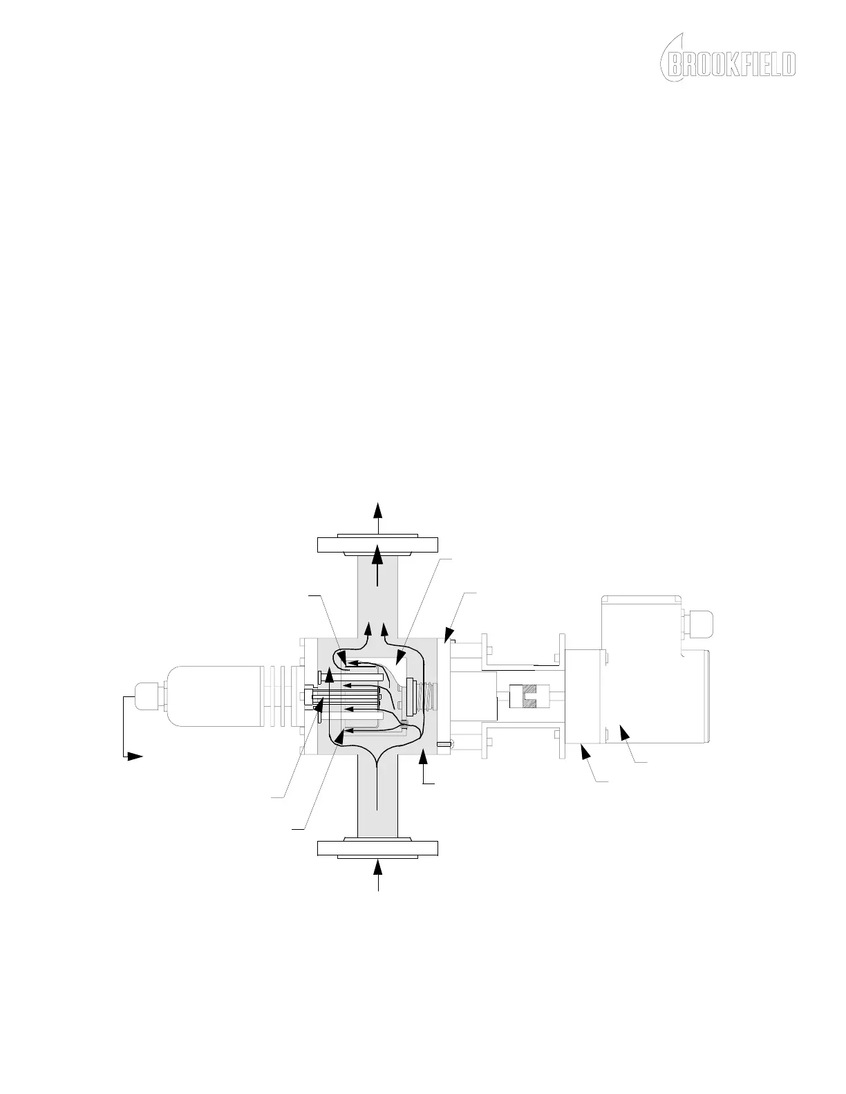
Theory of Operation
The product stream flows through the inlet into the TT100 In-Line
Viscometer measuring chamber, as shown in Figure 1-3, where it pushes
against a cylinder or rotor driven by a drive motor. The rotation of the rotor
causes a gentle pumping action forcing the product to flow into the
measuring annulus between the rotor and the stator. The viscous drag of the
product on the stator is resisted by a torsion element which transmits an
angular deflection signal to a rotary transformer drive transducer. This
signal is processed through solid state torque sensor electronics in a remote
enclosure to produce a linear 4 - 20 mA signal proportional to the
viscometer’s viscosity range.
Measuring range and shear rate can be varied by changing rotational speed
(via gearbox or by speed control) or by changing the rotor and/or stator as
specified in Table D-1. Refer to Appendix D for more information on
changing geometrical components.
Figure 1-3: TT100 In-Line Viscometer Product Stream Flow
TORSION ELEMENT
STATOR
MEASURING ANNULUS
MEASURING CHAMBER
DRIVE MOTOR
ROTOR
INLET
OUTLET
PRODUCT
STREAM
PRODUCT
STREAM
DRIVE ENDCAP
OUTPUT SIGNAL
TO ENCLOSURE
GEARBOX