Calibration
3-16 P/N M/97-520
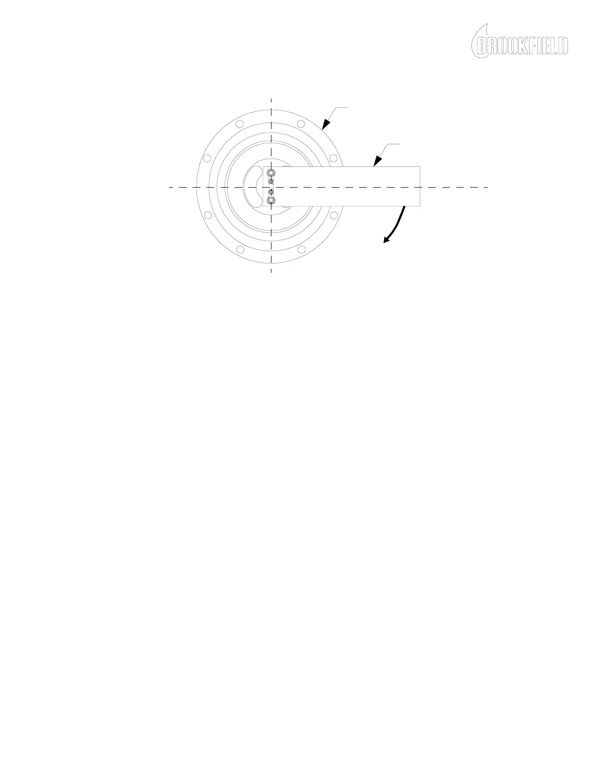
Figure 3-7: Calibration Bar Installation
16. Adjust R51 for the HIGH range mA value shown on the Viscometer
Specification Sheet.
NOTE: If 4.00 ± .02 mA cannot be achieved in step 16, refer to Appendix
A and call Brookfield Engineering Laboratories, Inc. for assistance.
17. Remove the calibration bar. The DVM should indicate
4.00 ± .02 mA.
18. Remove the range jumper wire from J2-Pin 3 and connect it to
J2-Pin 2 (LOW range).
19. Observe the DVM reading.
NOTE: If 4.00 ± .05 mA is not displayed on the DVM after switching the
range jumpers, then perform the Fine Zero Voltage Calibration procedure.
20. Install the lightest of the two calibration bars, that came with your
viscometer, on the stator mounting screws, parallel to the work
surface as shown in Figure 3-7.
21. Adjust R20 for the mA LOW range value shown on the Viscometer
Specification Sheet.
NOTE: If 4.00 ± .02 mA cannot be achieved, refer to Appendix A and call
Brookfield Engineering Laboratories, Inc. for assistance.
22. Remove the calibration bar. The DVM should indicate
4.00 ± .02 mA
23. Repeat steps 11 - 22 to ensure calibration repeatability.
CALIBRATION BAR
SENSING END CAP ASSEMBLY
T
O
R
Q
U
E
NOTE: Torque may be applied in the opposite direction for some viscometer models.