Installation
2-4 P/N M/97-520
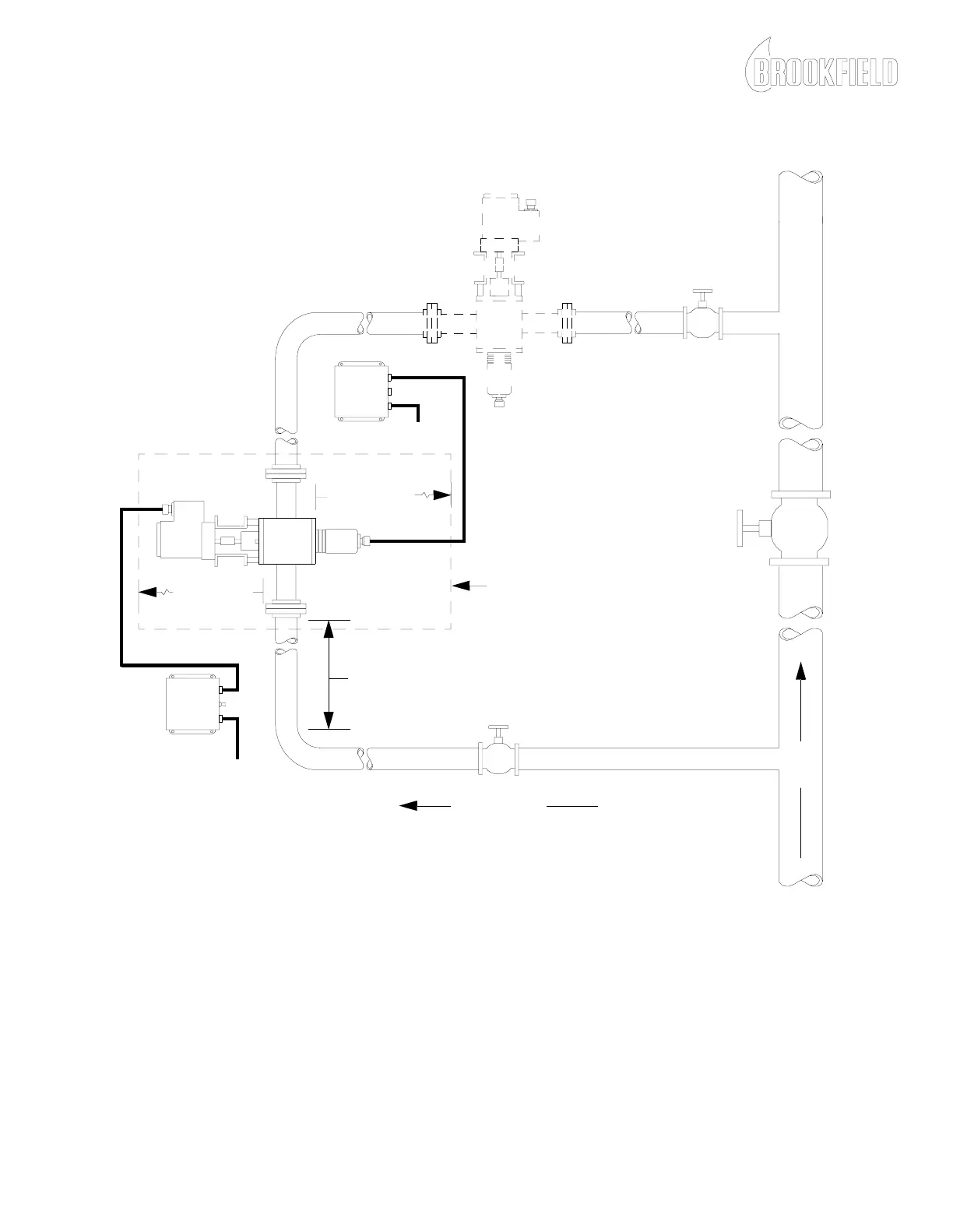
Figure 2-1: Typical In-Line Viscometer Installation
MAIN
LINE
BYPASS FLOW
0.5 - 20 GPM
14 INCH MINIMUM
CLEARANCE
16 INCH MINIMUM
CLEARANCE
PREFERRED
INSTALLATION
ALTERNATE
INSTALLATION
MOTOR
CONTROL
ENCLOSURE
TORQUE SENSOR
ENCLOSURE
ELECTRONICS
PIPE DIAMETER X 10 = MINIMUM STRAIGHT PIPE LENGTH
115 or 230 VAC
50 or 60 HZ
NOTE: For all viscometers, position the drive endcap bleed screw in the UP position to
assist in the venting of gases.
NOTE: When installing the viscometer in the alternate position, rotate the viscometer on
the pipe axis to minimize pockets where air or solids may collect.
115 or 230 VAC
50 or 60 HZ