Calibration
3-12 P/N M/97-520
CAUTION
Do not apply extra torque beyond that which is provided by the calibration
bar. Damage to the torsion element may result.
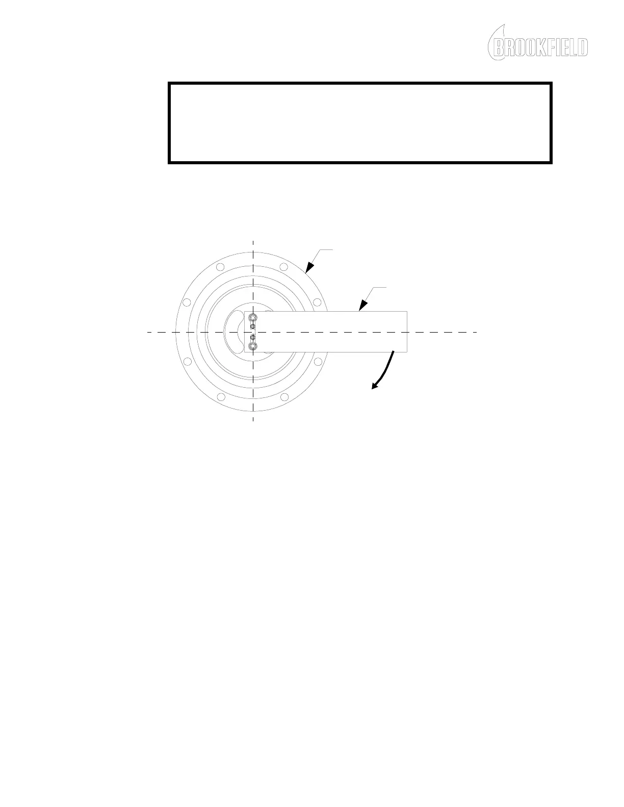
13. Install the calibration bar, that came with your viscometer, on the
stator mounting screws, parallel to the work surface, and in the
direction to which torque will be applied, as shown in Figure 3-6.
Figure 3-6: Calibration Bar Installation
14. Adjust R20 for the single LOW range or R51 for the single HIGH
range mA value shown on the Viscometer Specification Sheet.
15. Remove the calibration bar. The DVM should indicate
4.00 ± .02 mA.
NOTE: If steps 13 and 14 cannot be achieved, refer to Appendix A and
call Brookfield Engineering Laboratories, Inc. for assistance.
16. Repeat steps 12 - 14 to ensure calibration repeatability.
17. Turn power OFF to the torque sensor electronics enclosure.
18. Remove the DVM wire connections from the torque sensor
electronics circuit board.
CALIBRATION BAR
SENSING ENDCAP ASSEMBLY
T
OR
Q
U
E
NOTE: The viscometer may actually be calibrated to sense torque in either direction. The viscometer
motor can be wired to rotate in either direction. Calibration and the direction of rotation must be
matched. The standard calibration method is shown in Figure 3-6.