Maintenance
5-6 P/N M/97-520
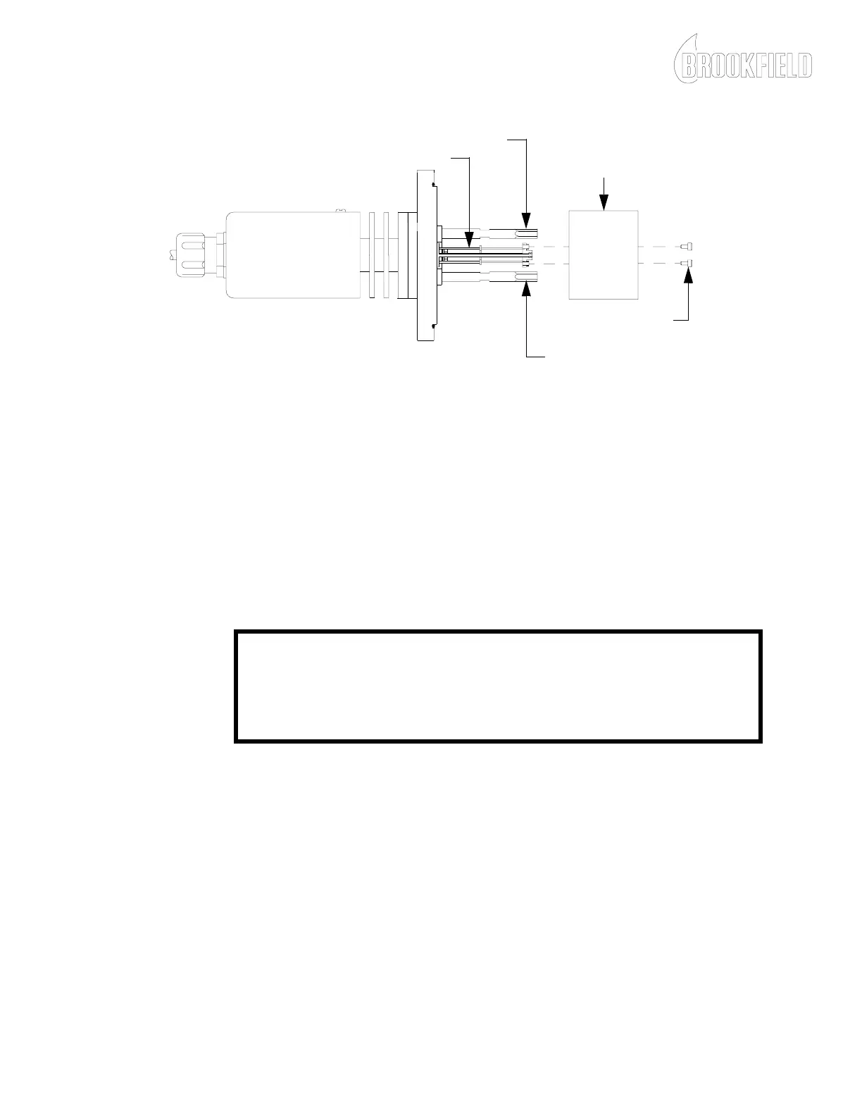
Figure 5-2: Typical Stator Removal and Torsion Element Wire Cleaning
5. Carefully install the stator and install the mounting screws but do
not tighten.
NOTE: The stop posts must be centered within the holes on the stator as
shown in Figure 5-3 to ensure free movement of the stator.
CAUTION
Do not apply torque to the torsion element while installing the stator
mounting screws. Damage to the torsion element may result.
6. With the stator mounting screws loose, rotate the stator so the stop
posts are aligned in the center of the holes in the stator as shown in
Figure 5-3. Tighten the stator mounting screws and check the
alignment of the stop posts.
STOP POST
STOP POST
STATOR
STATOR MOUNTING
SCREWS
TORSION ELEMENT WIRES
NOTE: There are many different versions of the sensing endcap. Your
viscometer may look different from the viscometer shown in Figure 5-2.