COPYRIGHT
©
1999 CANON INC. CANON GP160 REV.0 FEB. 1999 PRINTED IN JAPAN (IMPRIME AU JAPON)
CHAPTER 6 IMAGE FORMATION SYSTEM
6-5
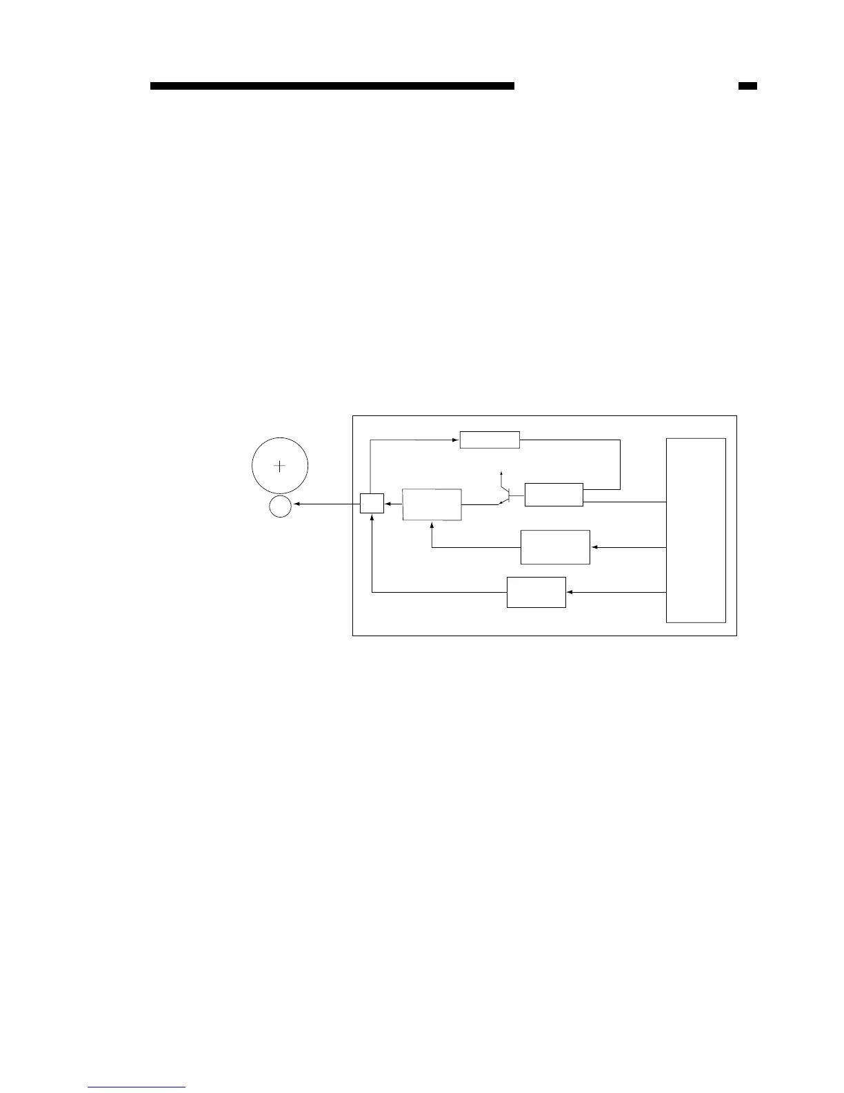
B. Bias control
The transfer charging roller bias is controlled by the DC controller PCB’s CPU
(IC301). When a positive bias drive signal (TRPWM) is output from CPU, the positive
bias generation circuit comes into operation.
Also, when a negative bias signal (TRNFOT) is output, the negative bias generation
circuit comes into operation.
As mentioned before, 4 types of bias are applied to the transfer charging roller at
designated times.
Furthermore, the transfer bias to the transfer charging roller is switched, depending
on the print resolution (1200dpi equivalent and 600dpi equivalent) of this unit.
By means of the bias switching signal (1200DPI) from the CPU, the output voltage
from the positive bias generation circuit and negative bias generation circuit switches
over.
Figure 6-301
+24V
Transfer charging roller
Positive bias
generation
circuit
Negative
bias
generation
Fixed voltage
control
Bias switching
Comparison
circuit
CPU
(IC301)
DC controller PCB
[1] TRPWM
[2] 1200DPI
[3] TRNFOT
JH403
[1] TRPWM: Positive bias drive signal
[2] 1200DPI: Bias switching signal
[3] TRNFOT: Negative bias switching signal
Photo-
sensitive
drum
Super-
impose