COPYRIGHT
©
1999 CANON INC. CANON GP160 REV.0 FEB. 1999 PRINTED IN JAPAN (IMPRIME AU JAPON)
CHAPTER 4 IMAGE PROCESSING SYSTEM
4-2
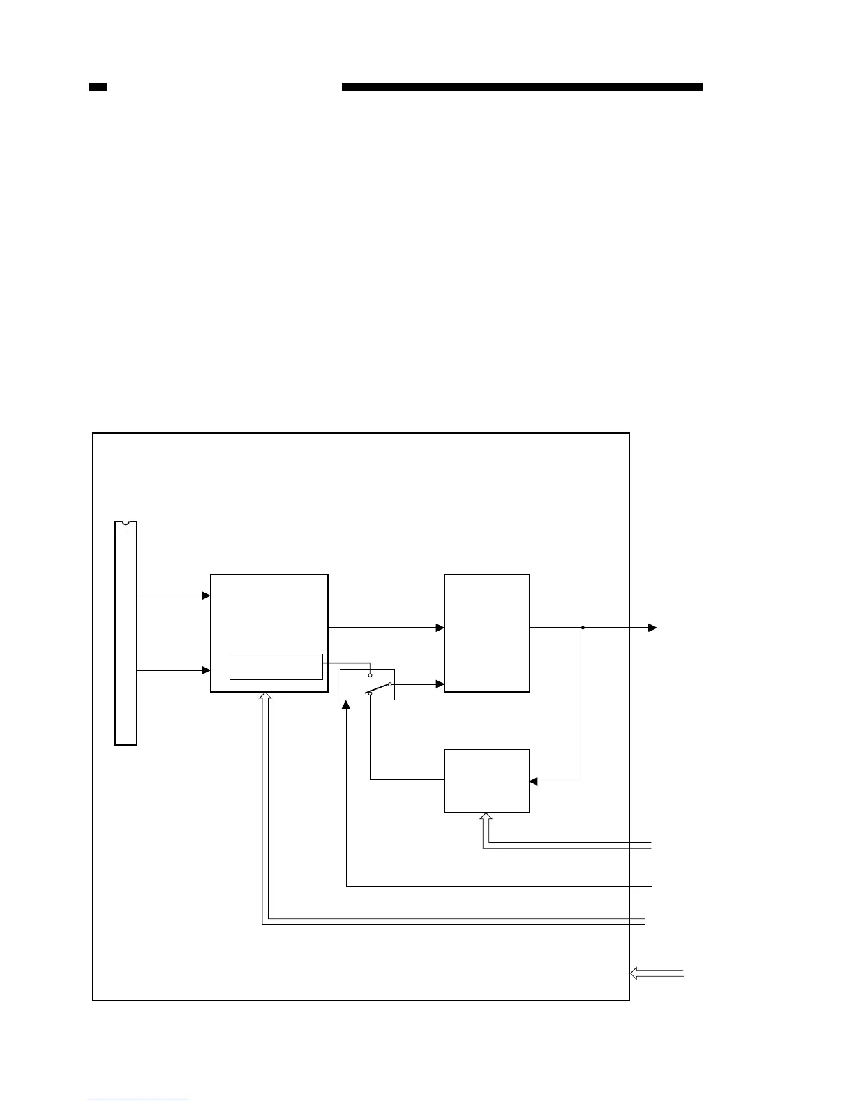
II. ANALOG IMAGE PROCESSING
A. Overview
The analog processor PCB converts the CCD drive control and CCD output signals
(analog signals) into digital signals. It also controls the AE.
B. CCD/CCD drive circuit
The CCD is a linear image sensor with 5000 pixel per line (light receiving unit). The
signal which has undergone photoelectric conversion at the light receiving unit is output
separately as even number pixels and odd number pixels, and is transmitted to the CCD
drive circuit. The CCD drive circuit then synthesizes the separately output odd number
and even number pixel signals, and outputs the synthesized signal to the A-D conver-
sion circuit.
Figure 4-201