EasyManua.ls Logo

Canon GP160DF - Image Leading Edge Margin Adjustment; Attaching the Scanner Wire

Canon GP160DF
797 pages
Print Icon
To Next Page IconTo Next Page
To Previous Page IconTo Previous Page
Loading...
CHAPTER 2 STANDARDS AND ADJUSTMENTS
2-2
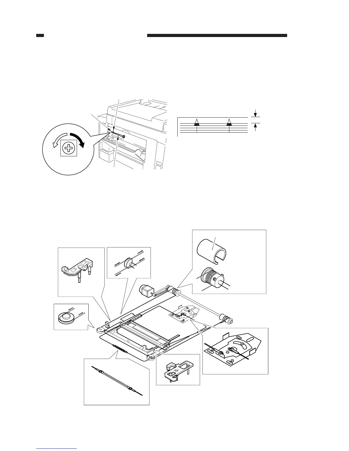
2. Image leading edge margin adjustment
Adjustment when the leading edge of the printed image is out of alignment.
a) Use a precision screwdriver to press down on SW401 and output a test print.
b) Turn VR401 and adjust the leading edge margin of the test print to 4.0 ± 2.0mm.
Figure 2-2
3. Attaching the scanner wire
Attach the wire, following steps 1 to 9. Then perform the mirror positioning adjust-
ment described on the next page.
Figure 2-3
Precision screwdriver (3mm)
VR401
VR401
SW401
4.0 ± 2.0mm
Pulley clip
[1]
[2]
[2]
[3]
[4]
[5]
[6]
Put the steel
ball into the
pulley hole.
Wrap the wire
2 times to the
inner side and
7 times to the
outer side.
Then, attach
the pulley clip.
Attach the mirror
positioning plate.

Table of Contents

Other manuals for Canon GP160DF

Related product manuals