COPYRIGHT
©
1999 CANON INC. CANON GP160 REV.0 FEB. 1999 PRINTED IN JAPAN (IMPRIME AU JAPON)
CHAPTER 10 CASSETTE FEEDER
10-3
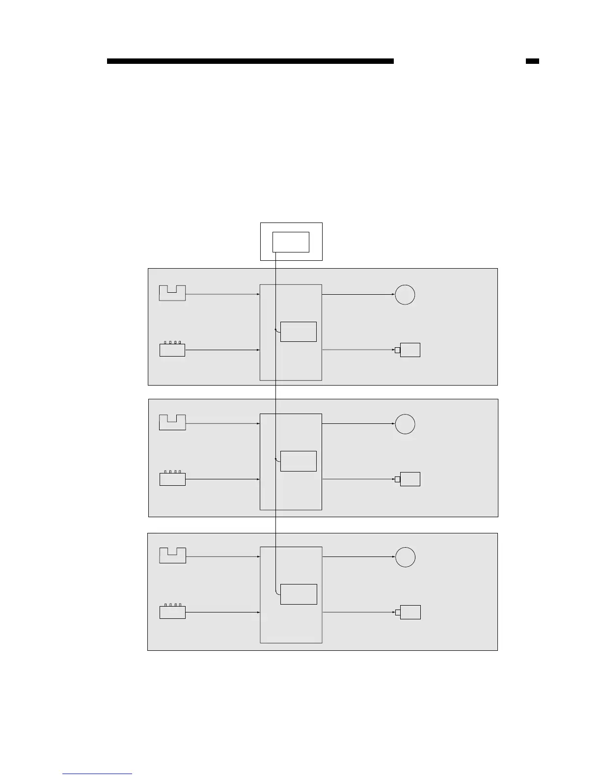
II. OVERVIEW OF THE ELECTRICAL CIRCUITS
A. Overview
Operation of the load used by the cassette feeder is controlled by commands sent
from the CPU (IC301) on the main unit’s DC controller PCB, based on the programme
stored in the CPU (IC601) on the feeder controller PCB.
Figure 10-201
Cassette feeder (3rd level)
Cassette feeder (2nd level)
Switch
• Cassette size detector
switch
Solenoid
• Pick-up solenoid (SL651)
Motor
• Feeder motor (M651)
[Input side]
[Output side]
Feeder controller
PCB (first level)
CPU
(IC601)
CPU
(IC301)
DC controller PCB
Photo-interrupter
• Pick-up sensor (PS651)
• Paper supply sensor (PS652)
Switch
• Cassette size detector
switch
Solenoid (SL651)
• Pick-up solenoid
Motor
• Feeder motor (M651)
Feeder controller
PCB (2nd level)
CPU
(IC601)
Photo-interrupter
• Pick-up sensor (PS651)
• Paper supply sensor (PS652)
Switch
• Cassette size detector
switch
Solenoid (SL651)
• Pick-up solenoid
Motor
• Feeder motor (M651)
Feeder controller
PCB (3rd level)
CPU
(IC601)
Photo-interrupter
• Pick-up sensor (PS651)
• Paper supply sensor (PS652)
Cassette feeder (first level)