COPYRIGHT
©
1999 CANON INC. CANON GP160 REV.0 FEB. 1999 PRINTED IN JAPAN (IMPRIME AU JAPON)
CHAPTER 6 IMAGE FORMATION SYSTEM
6-6
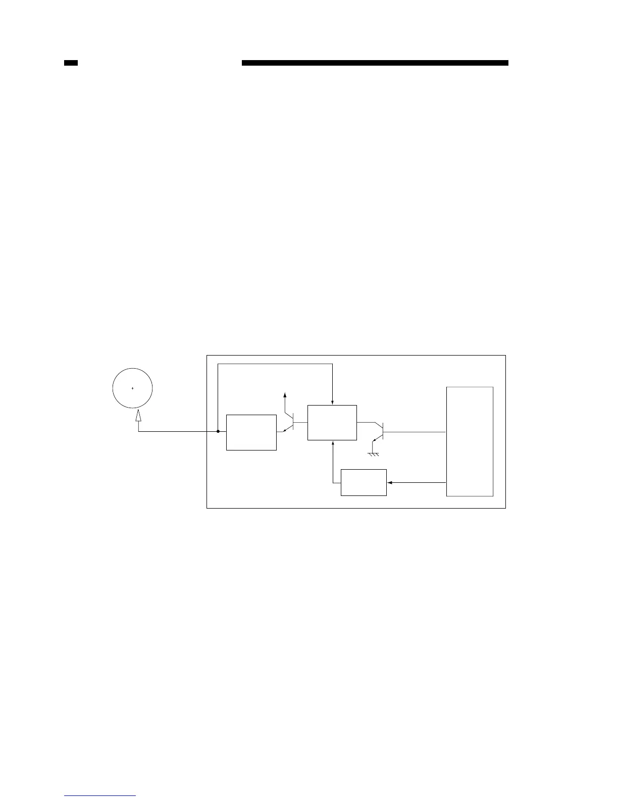
IV. SEPARATION STATIC CHARGE ELIMINATOR BIAS
CONTROL
A. Operation
The separation static charge eliminator is controlled by the DC controller PCB’s CPU
(IC301)
When a separation static charge eliminator bias ON signal (DCSON) is output from
the CPU, the drive circuit transformer T406 comes into operation and negative voltage is
applied to the separation static charge eliminator.
Also, when output voltage from the transformer T406 is returned to the bias drive cir-
cuit, the constant voltage control is performed in order to output a fixed voltage.
Furthermore, the separation static charge eliminator supply bias is switched depend-
ing on the print resolution (1200dpi equivalent and 600dpi equivalent) of this unit,.
The bias drive circuit, by means of the bias switching signal (1200DPI) from the
CPU, judges the print resolution and the switches the output voltage.
Figure 6-401
 Loading...