Home
Canon
Printer
GP160DF
Page 176
Canon GP160DF - Page 176
797 pages
Manual
Save Page as PDF
To Next Page
To Next Page
To Previous Page
To Previous Page
Loading...
COPYRIGHT
©
1999 CANON INC. CANON GP160 REV.0 FEB. 1999 PRINTED IN JAPAN (IMPRIME AU JAPON)
CHAPTER 9 EXTERNAL/AUXILIARY MECHANISM
9-18
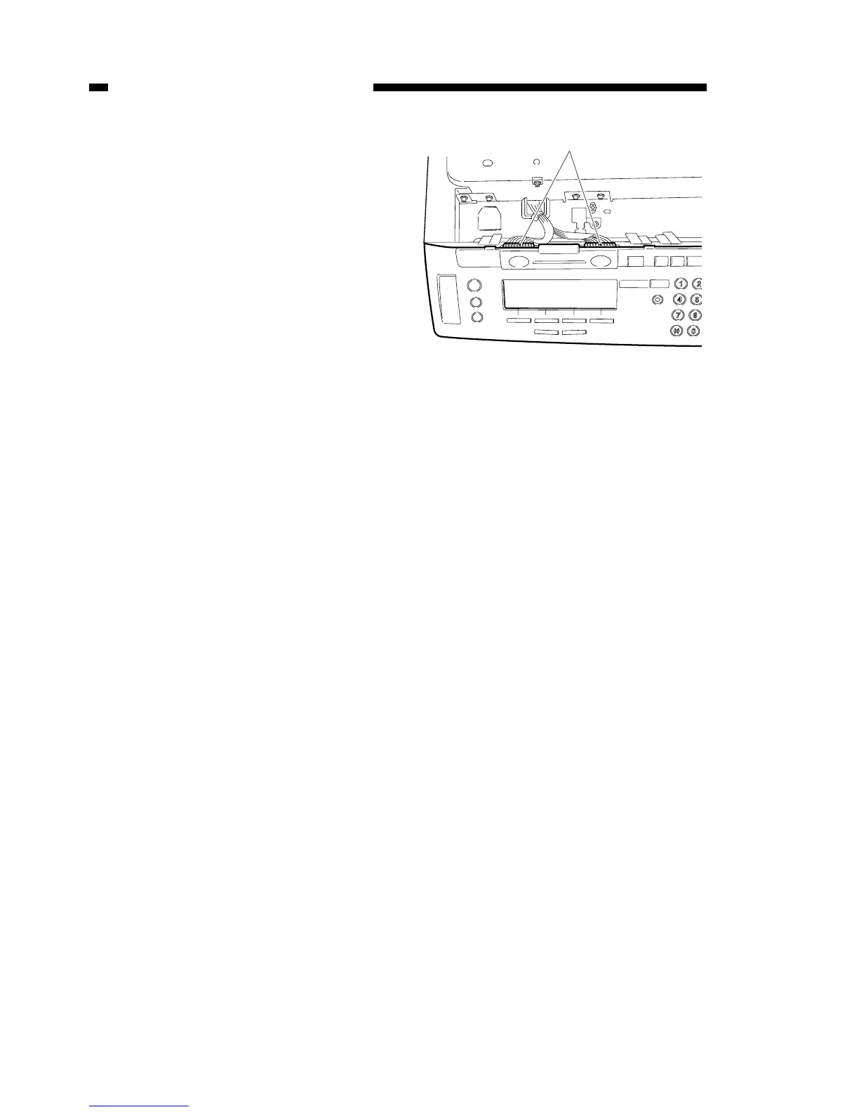
4
)
Mo
ve the control panel f
orward,
remov
e the 2 connectors [4], and
remov
e the control panel.
Figure 9-504
[4]
175
177
Table of Contents
Main Page
Table of Contents
7
Default Chapter
1
Service Manual
1
Chapter 1 Introduction
13
Features
13
Specifications
14
II. Specifications
14
Names of Parts
18
External View
18
III. Names of Parts
18
Cross Sectional Diagram
20
Operation Explanation
22
Control Panel
22
Basic Operation
25
Advanced Features
25
Chapter 2 Basic Operation
25
User Mode
26
Routine Maintenance to be Carried out by the User
44
Safety
45
Laser Beam Safety
45
Handling the Laser Unit
47
Toner Safety
48
Copying Process
49
Outline
49
Chapter 2 Basic Operation
51
Basic Operation
53
Function Configuration
53
Copy Operation Overview
54
Electrical Circuit Overview
55
Basic Sequences
56
III. Basic Sequences
56
Main Motor
57
IV. Main Motor
57
Principal Circuit Pcb Input/Output
58
Chapter 3 Exposure System
63
Exposure System
63
Operation Overview
65
Overview
65
Exposure System Sequence
66
Scanner Drive System
67
Document Scanner Motor
67
Scanning Lamp Control
68
Disassembly, Assembly
69
III. Disassembly, Assembly
69
Scanning Lamp
70
Document Scanning Motor
72
Chapter 4 Image Processing System
73
Overview
75
Overview
76
Analog Image Processing
76
CCD/CCD Drive Circuit
76
II. Analog Image Processing
76
A-D Conversion Circuit / ABC Circuit
77
Digital Image Processing
78
Overview
78
Shading Correction
79
Magnification Ratio Process
81
Edge Emphasis / Smoothing Process
81
Logarithmic Correction
82
Half Tone Density Processing
83
Binarisation
83
Disassembly, Assembly
84
CCD Unit
85
Chapter 5 Laser Exposure System
87
Laser Exposure System
87
Overview
89
Bd Signal Generation
91
Overview
91
BD Generation / Detection
91
II. Bd Signal Generation
91
Laser Driver Circuit
92
Operation
92
Laser Light Intensity Control
92
Laser Scanner Motor Control
94
Operation Outline
94
Disassembly, Assembly
95
Laser Scanner Unit
96
Chapter 6 Image Formation System
97
Image Formation System
97
Overview
99
Construction
99
Primary Charging Roller Bias Control
101
Outline
101
Control Operation
101
Transfer Charging Roller Bias Control
102
Overview
102
Bias Control
103
Separation Static Charge Eliminator Bias Control
104
Operation
104
Developing Bias Control
105
Outline
105
Operation
105
Re-Charge Bias Control
106
Operation
106
Cartridge Detection
107
Operation
107
VII. Cartridge Detection
107
Chapter 7 Pick-Up / Feeding System
109
Overview
111
Construction Overveiw
111
Pick-Up Feeding Operation
112
Cassette Pick-Up Mechanism
113
Pick-Up Oparation
113
Retry Pick-Up
115
Paper Size Detection
116
Multi-Feeder Pick-Up
117
Overview
117
Multi-Feeder Pick-Up Mechanism
118
Multi-Feeder Retry Pick-Up
119
Multi-Feeder Paper Size Setting
120
Paper Feeding Operation
122
Paper Leading Edge Detection
122
Paper Width Detection
122
Jam Detection
123
Overview
123
VI. Jam Detection
123
Types of Jam
124
Jam Sequence
124
Disassembly, Assembly
133
VII. Disassembly, Assembly
133
Cassette Feeding Assembly
134
Multi-Feeder Assembly
140
Registration Roller Assembly
143
Feeder Assembly
145
Chapter 8 Fixing System
147
I. Operational Overview
147
Operational Overview
149
Overview
149
Fixing Pressure Roller Cleaning
149
Fixing Control
151
Fixing Temperature Control
151
Fixing Assembly Malfunction Detector
153
Fixing Heater Safety Mechanism
153
Disassembly, Assembly
154
Removing the Fixing Assembly
155
Chapter 9 External / Auxiliary Mechanism
157
Control Panel
159
Overview
159
Power Supply
160
II. Power Supply
160
Low-Voltage Power Supply Circuit
160
High Voltage Power Supply Circuit
162
Energy Save Function Control
163
Fan
165
III. Fan
165
Rotation Control Mechanism
165
Back-Up Battery
166
Back-Up Function
166
Back-Up Data
170
Disassembly, Assembly
174
Control Panel
175
Main Motor
177
DC Controller PCB
183
Image Processor PCB
184
DC Power Supply PCB
185
Chapter 10 Cassette Feeder
187
Overview
189
Overview
191
Overview of the Electrical Circuits
191
Feeder Controller Pcb
191
II. Overview of the Electrical Circuits
191
Feeder Controller Pcb Input and Output
192
Operation Overview
193
Overview
193
Basic Sequence
194
Feeder Motor Control
195
Operation
195
Jam Detection
196
Overview
196
VI. Jam Detection
196
Jam Sensing
197
Disassembly, Assembly
199
VII. Disassembly, Assembly
199
Removing the Feeder Motor
200
Removing the Pick-Up/Feeder/ Separation Motor
200
Removing the Pick-Up Unit
202
Chapter 11 Installation
205
Choosing an Suitable Installation Location
207
Unpacking and Installation
209
Opening the Package and Removing the Packing Materials
210
Installing the Cartridge
211
Loading Paper into the Cassette
214
Loading Paper into the Multi-Feeder
217
Attaching the Tray/Power Cord
218
Checking the Copy Image
219
Setting the Fax Machine Function
219
Service Mode
219
Chapter 12 Maintenance and Inspection
223
Maintenance and Inspection
223
Estimated Lifespan of Consumable Parts
225
Periodic Replacement Parts
225
Basic Servicing Procedures
226
Cartridge Storage and Handling
227
Storage When the Packing Seal Is Intact
227
Storage and Handling When the Packing Seal Has Been Opened
228
Chapter 13 Troubleshooting
233
Troubleshooting
233
Standards and Adjustments
236
Electrical System
243
Image and Machine Malfunction Countermeasures
249
II. Image and Machine Malfunction Countermeasures
249
Initial Check
249
Treatment Procedures by Faulty Image Type
251
Operation Malfunction Countermeasures
260
Faulty Feeding Countermeasures
268
Overview
268
Copy Paper Jam
269
Faulty Feeding
272
Electrical Parts Positions/Functions
273
Clutches, Solenoids
274
B. Motor, Fan
276
Sensors
278
Switches, Lamps, Miscellaneous
280
Pcbs
282
Variable Resistor(Vr)/Led/Check Pin Listed by PCB Plate
284
Sensor Pcb
286
DC Power Supply Pcb
287
Service Mode
289
Overview
289
Operating Procedures
290
Service Mode Menu List
291
SSSW Default Setting
297
Parameter Settings
312
Test Mode (TEST MODE)
345
Reports
376
User Reports
376
Service Report
379
User Errors
397
Service Errors
404
Appendix
431
B. Signals and Abbreviations
435
Solvents and Oils
444
Table of Contents
449
Chapter 1 Maintenance and Servicing
451
Main Unit
451
Periodic Replacement Parts
451
Estimated Lifespan of Consumable Parts
451
Adf
452
Periodic Replacement Parts
452
Consumables Replacement Targets
452
C. Basic Servicing Procedures
453
D. Cartridge Storage and Handling
454
Chapter 2 Standards and Adjustments
459
Mechanical System
459
Right and Left Registration Adjustment
459
Image Leading Edge Margin Adjustment
460
Attaching the Scanner Wire
460
Mirror Positioning Adjustment
461
Printer Unit Receptacle Connector Mount Positioning Adjustment
464
Check the Pressure (Nip Width) of the Fixing Pressure Roller
464
Electrical System
466
Automatic Shading Adjustment
466
C. Adf Height Adjustment
472
D. Skew Feed Adjustment
474
E. Adjusting Image Position
476
Chapter 3 Arrangement and Functions of Electrical Parts
483
Clutches, Solenoids
484
Sensors
488
Switches, Lamps, Miscellaneous
490
Pcbs
492
Variable Resistor (Vr)/Led/Check Pin Listed by PCB Plate
494
Image Processor PCB
495
DC Controller Pcb/Sensor PCB
496
Feeder Controller PCB (Cassette Feeder)
498
Modem Board
499
NCU Board
500
Adf
501
Chapter 4 Service Mode
503
Overview
503
Operating Procedures
504
Service Mode Menu List
505
SSSW Default Setting
511
Parameter Settings
526
SSSW Settings
526
Menu Switch Settings (#2 MENU)
544
Numeric Settings by Type (#3 NUMERIC Param.)
546
Special Settings (#4A SPECIAL)
549
Country Type Setting (#5 TYPE)
551
Document Scanning Function Setting (#6 SCANNER)
551
Functions
552
ROM Information Display (#9 ROM)
557
CS SET (Mirror Mount Initialization Setting)
557
Test Mode (TEST MODE)
558
Overview
558
Test Mode Menu
559
D-RAM Test <1:DRAM
566
CCD Test <2:CCD TEST
567
PRINT Test <3:PRINT
567
MODEM NCU Test <4:MODEM NCU
569
AGING Test <5:AGING TEST
573
FACULTY Test <6:FACULTY TEST
573
BOOK Scanning Test <8:BOOK TEST
588
Service Errors
596
Appendix
624
Other
638
Copy Speed
639
Communication Section
640
Memory
641
Recording System
641
Scanning System
641
Dialing
642
Transmission Functions
642
Reception Functions
643
Activity Management Function
644
Parts Catalog
652
Table of Contents
658
Internal Components 1
665
Internal Components 2
668
Internal Components 3
672
Internal Components 4 (100V)
675
Scanner Drive Assembly
687
Main Drive Assembly
688
Multi Drive Assembly
690
Paper Pick-Up Assembly
693
Registration Roller Assembly
698
Paper Feed Belt Assembly
701
CCD Lens Mount Assembly
709
Fixing Assembly (100V)
710
Fixing Assembly (120/230V)
713
DC Controller Assembly
716
Flash Rom Pcb Assembly
718
Internal Components
735
Separation Assembly
738
Fax Kit
779
Other manuals for Canon GP160DF
Service Handbook
201 pages
Related product manuals
Canon GP160F
797 pages
Canon GP215
458 pages
Canon GP405
682 pages
Canon imagePROGRAF GP-300
32 pages
Canon ImagePrograf GP-4000
32 pages
Canon imagePROGRAF GP-5300
877 pages
Canon G570
44 pages
Canon G3411
356 pages
Canon GX7050
60 pages
Canon GX7010
28 pages
Canon PIXMA G670
431 pages
Canon PIXMA G620
431 pages