172 SECTION 55 - ELECTRICAL SYSTEM
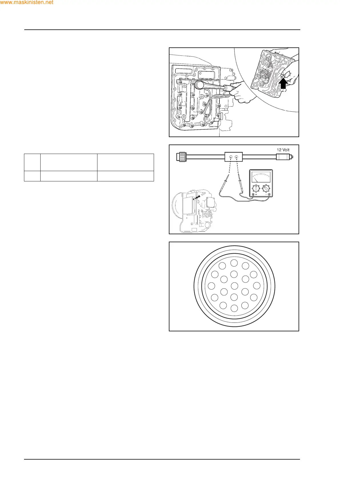
POWERSHIFT SPEED SENSOR TEST
Disconnect from control valve and fit the 12 pin con-
nector from special tool.
Connect the power socket to the 12 V socket.
Install the probes from a multimeter into the tool.
Raise the unit off the ground and observe voltage
(V1). Turn the rear wheel which in turn rotates the
transmission output shaft, observe the second volt-
age (V2).
Test procedure
The special tool connects to pin A speed sensor plus
output, and pin J speed sensor/temperature sensor
ground.
Description
A Speed sensor +
B FWD request
C Disconnect request input
D Speedometer output
E Diagnostics link input
F Analogue Input 1
G Analogue Input 0
H-
J-
K PWM solenoid supply
L Solenoid 3
MPWM 1
N Range solenoid 27
P Forward solenoid
R Solenoid 2
S Solenoid 1
TVCS
UGround
VBattery +
Pin
No.
V1 V2
A 0.6 - 0.8 1.3 - 1.5
F28394
F28397
F28398
A
B
C
D
E
F
G
H
J
K
L
M
N
P
R
S
T
U
V
 Loading...


