SECTION 55 - ELECTRICAL SYSTEM 171
POWERSHIFT CONTROL UNIT
The control unit receives the signals switching ON or
OFF the solenoids and allowing the desired gears to
be selected. A variable current solenoid receives a
reducing signal from the EGS controlling modulator.
The control unit is equipped with a combined tem-
perature and speed sensor which sends signals
back to the EGS.
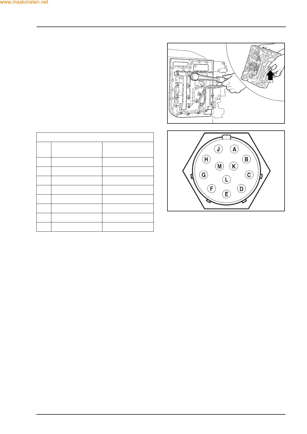
Test Procedure
Test between pin indicated in the left hand column
and either pin H or M as detailed in the table below.
* A Speed sensor plus output 24
B Forward Lo/Hi solenoid
C Forward/neutral solenoid
D Range 1/2 solenoid
E FWD solenoid
F Reverse neutral solenoid
G Direction modulation solenoid
K Range modulation solenoid
L Transmission temperature out ground
M Control valve common plus
DESCRIPTION
Pin
No.
HM
A
27.5 Ω -
B
27.5 Ω -
C
27.5 Ω -
D
27.5 Ω -
E
27.5 Ω -
F
27.5 Ω -
G
-14 Ω
K
-31 Ω
F28394
F28395
 Loading...


