170 SECTION 55 - ELECTRICAL SYSTEM
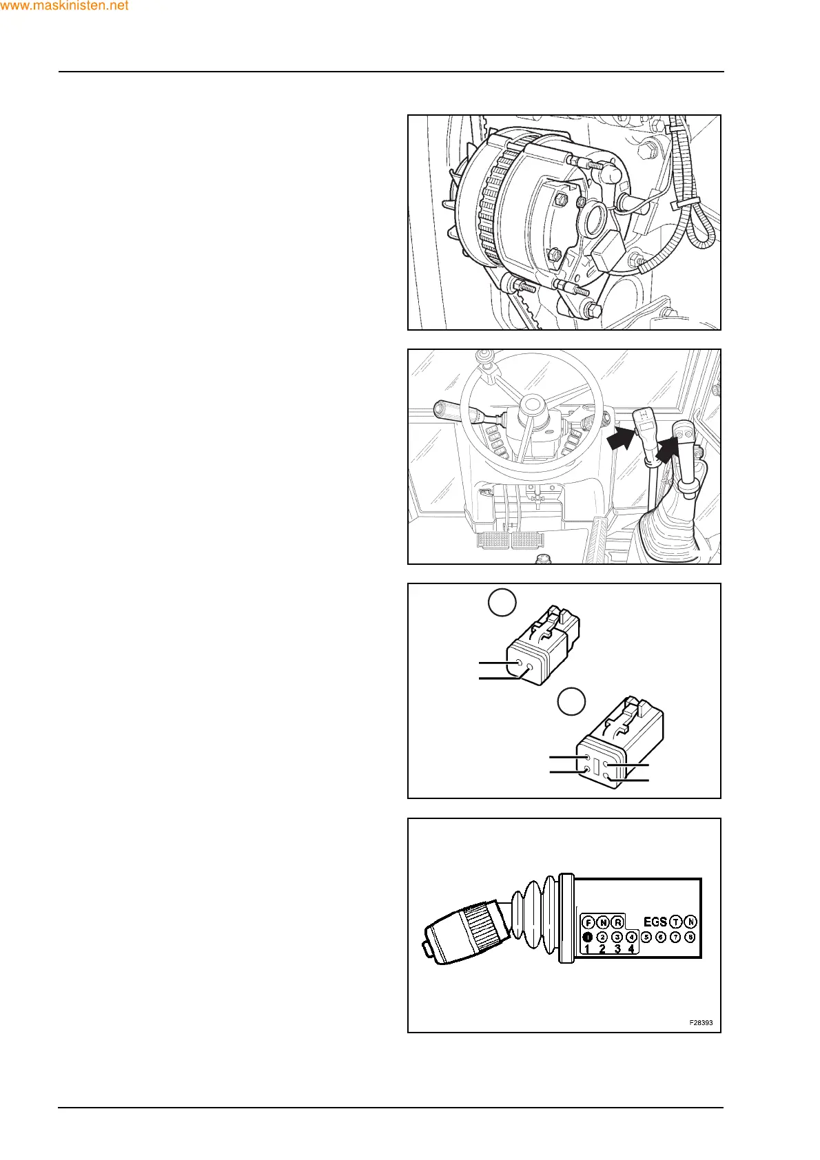
8.5 ALTERNATOR
This sends a square wave signal, the frequency of
which varies between 142.52 855 Hz (480 - 3060
rpm) to the instrument panel.
With the engine running, the warning light should
turn off. If not, disconnect the wire connected to the
terminal D+ (pink wire).
When D+ is not connected and the warning light
goes out, there is a fault with the alternator. If it does
not turn off, then check the bulb and the wiring loom.
8.6 TRANSMISSIONS
POWERSHUTTLE DISCONNECT - X23/X28
Energizes the transmission dump solenoid at 12 V.
Test procedure
Continuity should be found between pin 1 and pin 2
when switch is operated.
POWERSHIFT EGS CONNECTOR
The EGS receives input from the FWD Switch,
brakes, switches, transmission disconnect switch,
temperature sensor and speed sensor. The EGS
also sends signals to the transmission control valve.
For input and output tests to check correct operation
of the EGS, refer to Section 21.
Test Procedure
Test procedure of the speed sensor refer to the next
page.
F28388
F28392
F28391
2: RM:A-R:1
4: RM:C-N:1
3: RM:N:1
2: RM:A-R:1
1: RM:B-R:1
1: RM:B-R:1
X23
X28
 Loading...


