30 SECTION 35 - HYDRAULIC SYSTEM
Two or more hydraulic circuits operating
When two or more hydraulic systems operate, each
system will operate at a different pressure.
If pump flow to a specific system is not controlled,
the system requiring a lower operating pressure will
work faster than the system requiring a higher pres-
sure, because the flow will have to overcome less
resistance.
To prevent this situation, the pressure compensat-
ing valve regulates the oil flow directed to the sys-
tem operating at a lower load.
When two spools are operated simultaneously
pump pressure is applied to the metering element of
the pressure compensating valve in both valve sec-
tions.
Both metering elements therefore move upwards al-
lowing oil to flow to the load check valves. At the
same time the aperture in the spool portion of the
pressure compensating valve is uncovered to allow
operating pressure to be sensed in the load sensing
gallery.
Pump pressure will rise until it exceeds the pressure
of the check valve of the system operating at the
heaviest load and the pressure in the load sensing
line has a value similar to that of the high pressure.
The pressure required to operate the system with a
lower load is now too high and, if not limited, it will
result in this system operating instead of and faster
than the system with a higher load.
To compensate for this condition, the load sensing
pressure moves the metering element of the pres-
sure compensating valve in the system with a lower
load downwards and restricts the flow to the system.
This balancing of flow and pressure according to the
load ensures that both systems operate simultane-
ously and at a balanced flow rate.
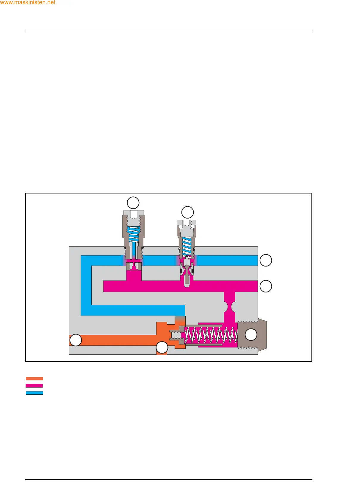
Load sense relief valve operating
Pump pressure at 210 bar
Load sense pressure at 195 bar
Return to oil tank
1. Load sense bleed orifice 1 l/min
2. Load sense limiter (system relief valve)
3. Return to oil tank
4. Load sense line
5. Pump flow balancer (unload) valve
6. Pump flow IN
7. To backhoe control valves
1
2
6
5
3
4
7
F29291