SECTION 35 - HYDRAULIC SYSTEM 113
6.3 DISASSEMBLY AND ASSEMBLY
Disassembly
Release pressure in the hydraulic circuits using the
following procedure: turn the starter switch key to ON
but do not start the engine. Turn pilot control cancel-
lation switch to the ON position. Move both joysticks
in all directions. Turn the starter switch key to OFF.
Disconnect the negative battery cables.
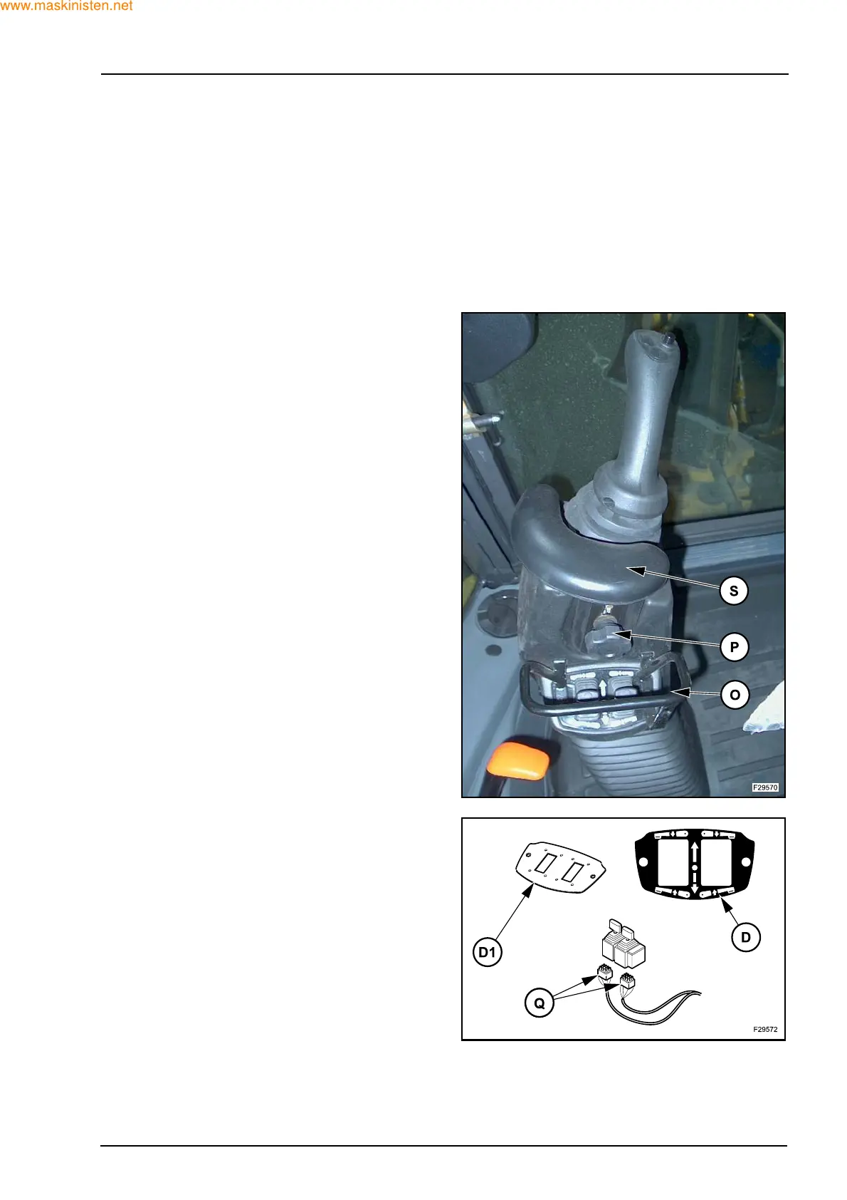
Z Mark the position of the lever parts (see the explod-
ed view on previous pages).
Z Remove the knob (P) and the support (S).
Z Remove the bracket (O) with the relevant screws
(with left hydraulic control lever).
Z Remove the decal (D), the mounting plate (D1) and
the detach the connectors (Q) (with left hydraulic
control lever).