114 SECTION 35 - HYDRAULIC SYSTEM
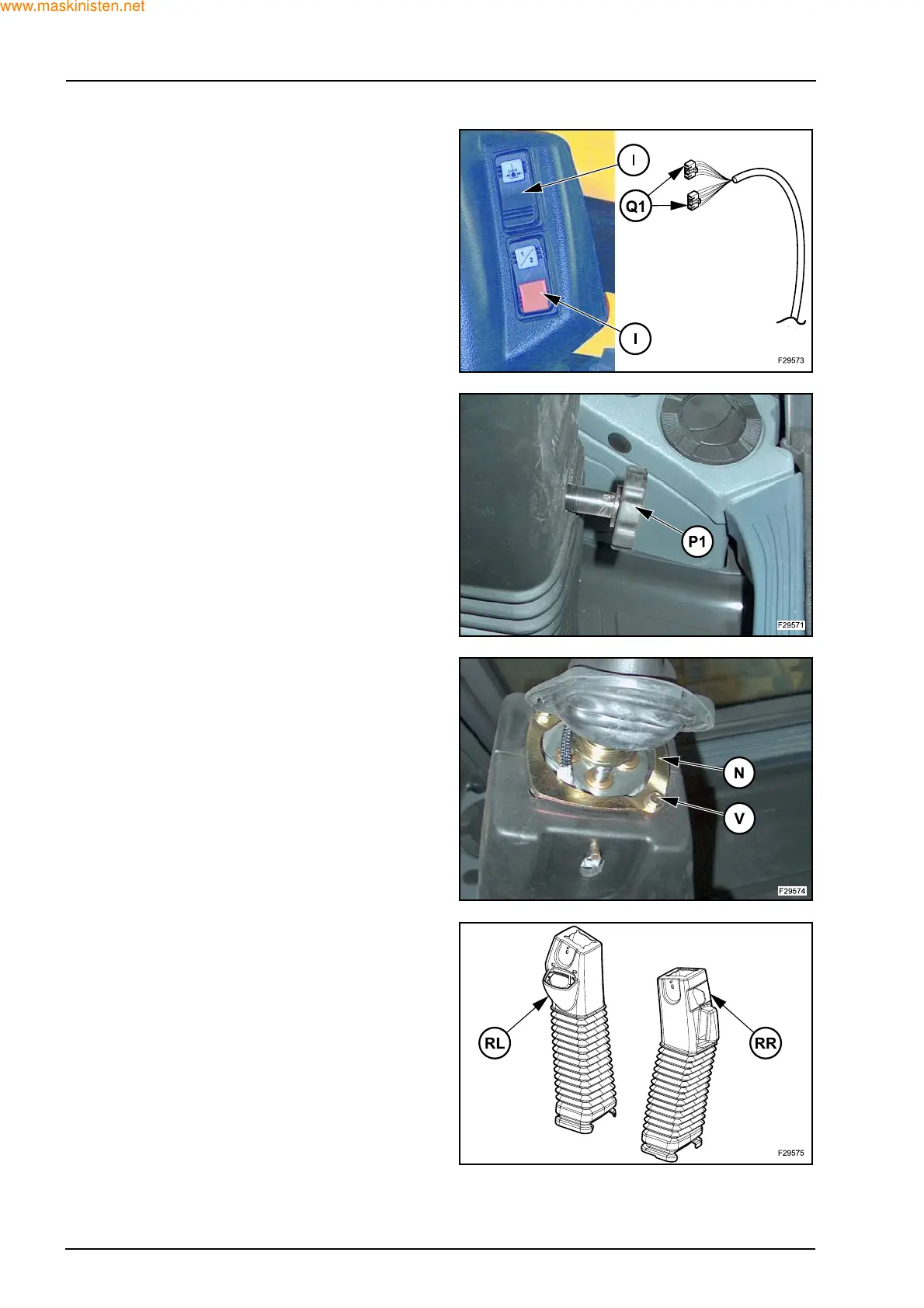
Z Pull out both switches (I) and the detach relevant
connectors (Q1) (with right control lever).
Z Remove the knob (P1) in the rear section of control
lever.
Z Remove the screws (V) and the plate (N).
Z Lift the rubber boot (RL) for left control lever and
the rubber boot (RR) for right control lever.