11
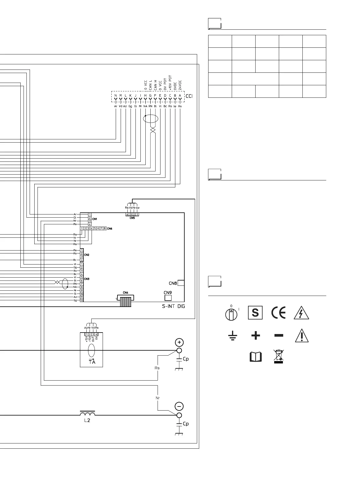
Key to the electrical diagram
•1 •2 •3 •4 •5
C2 CCI CHR Cp D2
•6 •7 •8 •9 •10
F-EMC IL L2 MIH MIL
•11 •12 •13 •14 •15
MV1-2 P1 P2 R2 RP
•16 •17 •18 •19
RS S-INT DIG S-INV S-LINK
•20 •21 •22 •23 •24
S-PS TA TH2 TP VR
•1 SNUBBER capacitor for output diodes •2 Interconnec-
tion cable connector •3 Cooling system power connector •4
Quick connection protection capacitor •5 Secondary diode
•6 EMC filter •7 Mains switch •8 Secondary inductor •9 Pri-
mary upper IGBT •10 Lower primary IGBT •11 Fan motor
•12 Main primary transformer (start) •13 Main primary trans-
former (end) •14 Output diode snubber resistor •15 Prima-
ry rectifier •16 Secondary rectifier •17 Digital interface PCB
•18 Inverter PCB •19 Capacitors PCB •20 Power Source
PCB •21 Hall effect transformer •22 Secondary thermostat
•23 Main transformer •24 Output diodes snubber varistor
Colour key
Ar Orange
Az Sky Blue
Bc White
Bl Blue
Gg Grey
Gl Yellow
GV Yellow-Green
Mr Brown
NA Black-Sky Blue
Nr Black
RN Red-Black
Ro Pink
Rs Red
Vd Green
Vl Violet
Meaning of graphic
symbols on machine
9
8765
4321
10
•1 Power supply switch •2 System for use in environments
with increased risk of electroshock •3 Product suitable for
free circulation in the European Community •4 Danger! high
voltage •5 Grounding •6 Positive pole snap-in connector •7
Negative pole snap-in connector •8 Warning! •9 Before us-
ing the equipment you should carefully read the instructions
included in this manual •10 Special disposal