44
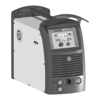
“HT4” CONTROL PANEL
WELDING MODE SELECTION LED
WELDING MODE SELECTION K
EY
WIRE KEY
ENCODER KNOB - A
PARAMETER SELECTION K
EY - A
PARAMETER SELECTION LED - A
PARAMETER DISPLAY S
CREEN - A
SPECIAL FUNCTIONS (FX) LED
SPECIAL FUNCTIONS (F
X) KEY
GAS KEY
ENCODER KNOB - V
PARAMETER SELECTION K
EY - V
PARAMETER SELECTION LED - V
PARAMETER DISPLAY S
CREEN - V
HOLD Function LED
PARAMETER DISPLAY SCREEN - A
Displays the value of the parameter WELDING CURRENT (
).
PARAMETER SELECTION LED - A
The LED unit shows the WELDING CURRENT (
) switched on.
ENCODER KNOB - A
Adjusts the WELDING CURRENT (
) parameter, interrupting the HOLD Function.
HOLD F
UNCTION LED Flashes for a set time, informing the operator that the HOLD Function is active.
PARAMETER DISPLAY S
CREEN - V Shows the parameter indicated by the PARAMETER SELECTION LED - V.
PARAMETER SELECTION LED - V
The LED unit indicates the welding parameter selected using the PARAMETER SELECTION K
EY
- V.
PARAMETER SELECTION K
EY - V
Scrolls in succession the parameters HOT START (
) - WELDING VOLTAGE ( ) - ARC
FORCE (
) only on the HT4 panel.
In this case the values displayed are those for HOLD (only for the welding voltage).
ENCODER K
NOB - V
Adjusts the parameter displayed by the PARAMETER DISPLAY S
CREEN - V interrupting the HOLD
Function.
SPECIAL FUNCTIONS (FX) KEY
Only enables entering, interrupting the HOLD Function and exit afterwards from the
SPECIAL FUNCTIONS Menu (SET UP Fx) on the HT4 panel and not on the DH panel.
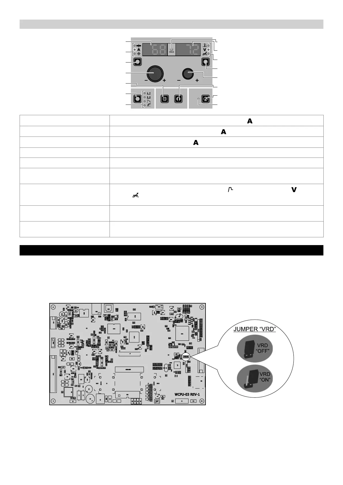
6 - ACTIVATING THE VRD DEVICE MMA
The Voltage Reduction Device (VRD) is a safety device that reduces voltage. It prevents voltages forming on the output termi-
nals that may pose a danger to people. The standard settings and those defined beforehand by do not provide for the VRD to be
active on the welding machine and so the VISION S
CREEN does not normally provide any indication.
If the operator wishes to weld in MMA using the VRD device (which must be done with the welding machine switched off), they must:
1) Use a suitable screwdriver to unscrew the 4 screws that fix the DH control panel to the welding machine.
2) Remove the “VRD” JUMPER on the DIGITAL INTERFACE PCB (see figure).
3) Use a suitable screwdriver to tighten the 4 screws that fix the DH control panel to the welding machine.
4) Start the welding machine by turning the switch on the rear panel to position I.
When it switches on, but with the machine in stand-by, the DH control panel shows that the VRD device is active (indication on
the VISION S
CREEN green colour - see enclosed image: MMA - PRE-SETTING).
During the welding phase the VRD device is activated (indication on the VISION S
CREEN red colour (does not indicate malfunction-
ing of the welding machine) - see enclosed image: MMA - WELDING) and when welding is ended the voltage will be reduced
within a maximum time of 0,3 seconds.