35
Special function
PARAMETER DISPLAY
Screen - A
PARAMETER DISPLAY Screen - V Welding mode
Default
Range
TWO STROKE (2T)
FOUR STROKE (4T)
CRATER 2T
CRATER 4T
SPOT WELDING
STITCH WELDING
CYCLE STANDARD
CYCLE ADVANCED
FINAL CRATER TIME F15 0.0s (0.0 - 5.0)s ●
BURN BACK bub 0 -30 - +30 ●●●●●●●●
POST GAS PoG 1.0s (0.0 - 10.0)s ●●●●●●●●
FIRST SLOPE ( I1 TO I 2 ) F18 0.05s (0.0 - 1.0)s ●
CYCLE WIRE SPEED F19 5.0m/min (0.6 - MAX)m/min ●●
CYCLE VOLTAGE F20 25.0V (min - MAX)V ●●
SECOND SLOPE ( I 2 TO I 1 ) F21 0.05s (0.0 - 1.0)s ●
ACS / ENCODER SPEED F28 100A/s (5 - 500)A/s ●●●●●●●●
WARNING:
• The STANDARD or ADVANCED welding CYCLE mode can only be activated by opening the ADVANCED SETUP Menu - AD-
VANCED MODE - CYCLE (for further explanations, see the relevant paragraph).
• It is possible to access editing of the SPECIAL FUNCTIONS (Fx) during welding.
•
Some of the values edited will be used immediately by the operator, while others will be active from when the next welding
task begins.
• The HOLD function is not active within the SPECIAL FUNCTIONS Menu (SET UP Fx).
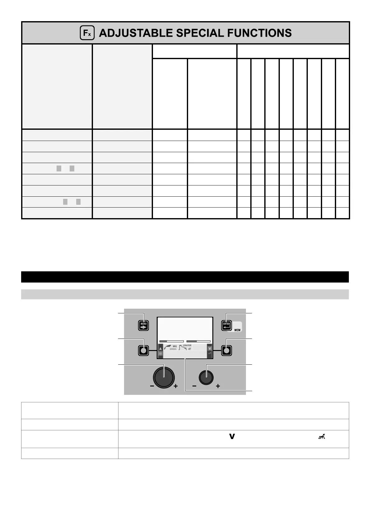
3 - PRE-SETTING MIG-MAG manual
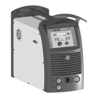
“DH” CONTROL PANEL
MENU KEY ENTER/MEM KEY
ENCODER KNOB - SX ENCODER KNOB - DX
VISION S
CREEN
SX KEY DX KEY
m/min V
7.8 31.3
MENU KEY
Used to access the PROCESS SELECTION Menu (PROCESS) and subsequent menus, as
applicable.
ENCODER K
NOB - SX Adjusts the parameter selected using the SX KEY.
DX K
EY
Scrolls in succession WELDING VOLTAGE ( ) - ELECTRONIC INDUCTANCE ( ) only on
VISION S
CREEN (this operation is activated when the key is released).
ENCODER K
NOB - DX Adjusts the parameter selected using the DX KEY.