4
Introduction
This manual describes the functions of the software operating the following control panels:
• DH 33 + HT4.
• DH 40 + HT4.
• DH 50 + HT4.
Functioning of the panels listed above is identical (the functions are the same but the characteristics differ depending on the type
of machine they are fitted on (e.g.: current regulation field).
General notes
•
Any adjustments/changes made on the welder control panel are also displayed automatically on the drag-and-drop
control panel and vice versa, the images on the displays of both weld system components could however differ one
from the other, as the displays are consistent with adjustments/changes but also independent as far as visualization
is concerned.
•
The adjustments / changes made are immediately available to the operator, unless indicated otherwise in the manual.
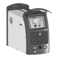
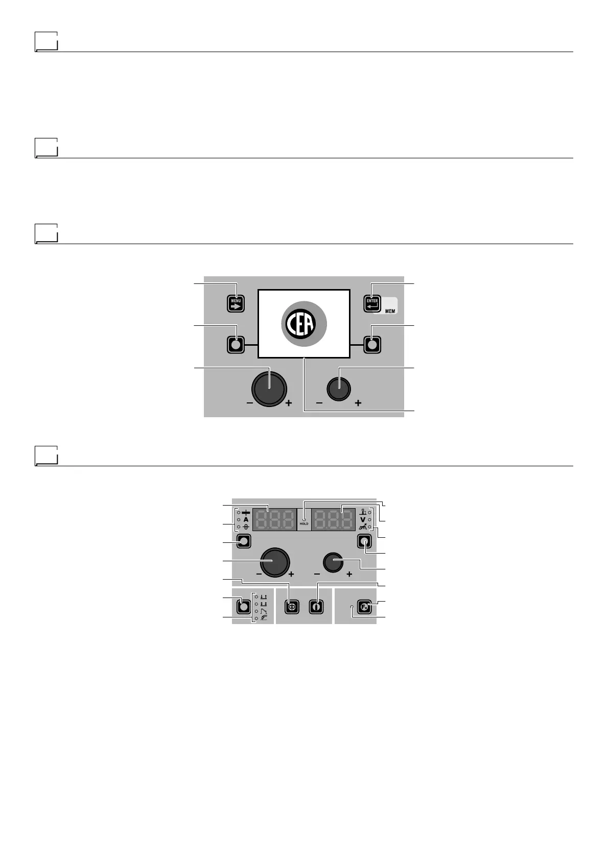
Welding machine control panel
The panel on the DIGITECH generator has four keys, two encoders, and a colour display. The figure below shows the panel. The
figure below shows the image of the panel.
MENU KEY ENTER/MEM KEY
ENCODER KNOB - SX ENCODER KNOB - DX
VISION SCREEN
SX KEY DX KEY
“DH” CONTROL PANEL
Wire feeder control panel
The HT4 wire feeder panel has 2 keys, 2 encoders and 7 LEDs in the upper section and 4 keys and 5 LEDs in the lower section.
The figure below shows the panel. The figure below shows the image of the panel.
WELDING MODE SELECTION LED
WELDING MODE SELECTION K
EY
WIRE KEY
ENCODER KNOB - A
PARAMETER SELECTION K
EY - A
PARAMETER SELECTION LED - A
PARAMETER DISPLAY S
CREEN - A
SPECIAL FUNCTIONS (FX) LED
SPECIAL FUNCTIONS (F
X) KEY
GAS KEY
ENCODER KNOB - V
PARAMETER SELECTION KEY - V
PARAMETER SELECTION LED - V
PARAMETER DISPLAY SCREEN - V
HOLD Function LED
“HT4” CONTROL PANEL