set is positive, the slave machine will track a posi-
tion higher than the master. Negative values will
cause the slave to track lower than the master.
SLAVE TILT
The program value “SLV TILT” is used to set the tilt
on the slave machine. It has the same valid range
as “RAM TILT”, which is used to set the tilt on the
master machine.
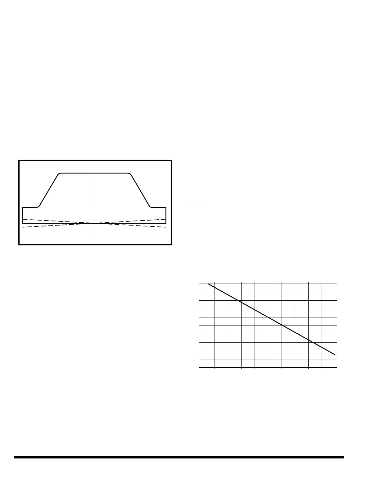
In Tandem Mode, tilt has a different effect than in
independent mode. Tilt does not affect the reversal
position of the ram at the center of the machine for
an independent machine. The two ends of the
machine are raised and lowered by half of the pro-
grammed tilt so the position of the ram at the cen-
ter remains unaffected. See Figure 8-6.
FIGURE 8-6 – Ram tilt in Single or Independent mode
For tandem machines, tilt does not affect the rever-
sal position of the ram at the inboard transducer.
The entire “RAM TILT” value is applied at the out-
board transducer of the master machine (right
transducer of the right hand machine). Positive
“RAM TILT” lowers the right end of the master
machine and negative “RAM TILT” raises the right
end of the master machine. On the slave machine,
the entire “SLV TILT” value is applied at the out-
board transducer (left transducer of the left hand
machine). Positive “SLV TILT” raises the left end of
the slave machine and negative “SLV TILT” lowers
the left end of the slave machine. See Figure 8-7.
Note: When tilts and offsets are used, the total avail-
able stroke length of the machine is reduced.
The ram will stop on the up stroke when the
highest cylinder reaches its maximum up
position. Likewise, the ram will stop on the
down stroke when the lowest cylinder reach-
es its maximum down position.
REVERSAL TONNAGE
When programming the reversal tonnage in Tan-
dem Mode, the maximum value becomes the com-
bined tonnage of both machines. For example,
when two 2000 FM Press Brakes are working in
tandem, the maximum tonnage that can be
entered is 4000 tons. The programmed tonnage
(and the tonnage displayed in the DIAGNOSTIC
screen) will only indicate the actual tonnage if a
bend the full length of both machines is made. For
bends shorter than full length, the actual tonnage
will be less than programmed or displayed.
To determine the program tonnage to be applied to
a part, use the bend length to select a Force Mul-
tiplier from the Tonnage Adjustment chart sup-
plied with your specific tandem machines. (This
chart will vary depending on the machine’s ton-
nage, nominal length and extension length(s). The
following chart is for 2000 FM tandem machines
with 20 ft. nominal length each and a 12 inch
extension on the inboard end of both machines.)
Multiply the required tonnage by the Force Multi-
plier and enter this value into the control. If this
value is more than the maximum value for the
tandem machines, enter the maximum value.
Example
: A 400 inch bend length part requires
1000 tons to form the part or to protect
the tooling. On the 2000 FM tandem
previously mentioned, the Force Multi-
plier from the Tonnage Adjustment
chart is 1.51. Multiply 1000 ton x 1.51
= 1510. Input 1510 for tonnage in the
program. This calculation assumes
that the part is centered about the tan-
dem centerline.
Tonnage Adjustment
LIGHT GUARDS
If a light guard is to be used to safeguard the
machine during tandem operation, the light guard
must be connected to the master machine and must
cover the entire workspace of the two machines. A
light guard connected to the slave machine will not
be active during tandem operation.