3-8
Catalyst 6500 Series Switches Installation Guide
OL-5781-04
Chapter 3 Installing the Switch
Installing the Rack-Mount Kit
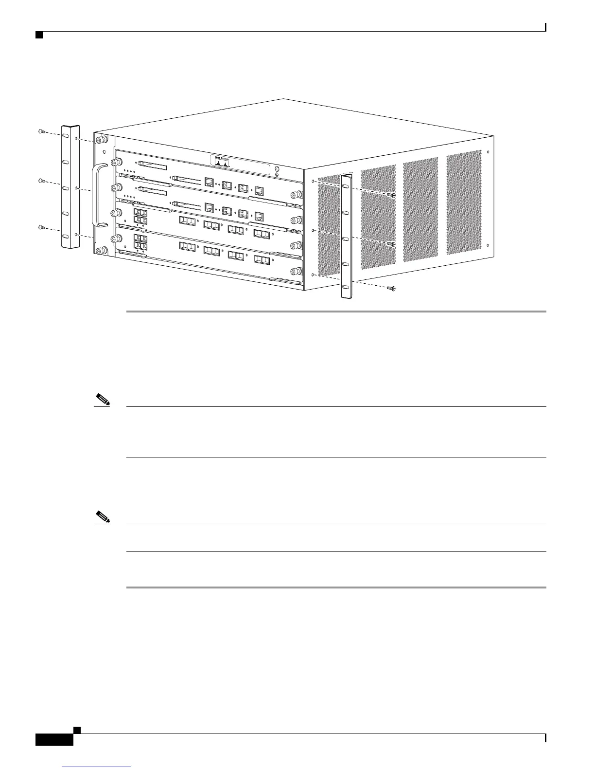
Figure 3-4 Installing the L-Brackets on the Catalyst 6504-E Switch Chassis
Installing the L Brackets and Cable Guides on the Catalyst 6506 and
Catalyst 6506-E Switches
Note The Catalyst 6506 and Catalyst 6506-E switch chassis is normally shipped with the L brackets installed.
If the chassis does not have the L brackets installed, follow the steps in this section to install the
L brackets on your Catalyst 6506 or Catalyst 6506-E switch chassis. You can also remove the L brackets
from the front of the chassis and reattach them to the rear of the chassis.
The L brackets attach to the Catalyst 6506 and the Catalyst 6506-E switch chassis with eight M3 Phillips
countersunk-head screws (four M3 screws on each side). Attach the optional cable guides by
sandwiching them between the L brackets and the switch chassis.
Note The L brackets for the Catalyst 6506 and Catalyst 6506-E switches are stamped with an L and an R to
identify them as left and right.
To install the L brackets and optional cable guides, follow these steps:
Step 1 Position the left (L) L bracket and the optional cable guide (if desired) against the switch chassis side,
and align the screw holes. (See Figure 3-5.)
Step 2 Secure the L bracket (and optional cable guide) to the switch chassis with four M3 screws.
Step 3 Repeat steps 1 and 2 for the right (R) L bracket (and, if necessary, the optional cable guide).
126562
S
T
A
T
U
S
S
T
A
T
U
S
FAN
S
TATUS