B-28
Catalyst 6500 Series Switches Installation Guide
OL-5781-04
Appendix B Transceivers, Module Connectors, and Cable Specifications
Cables
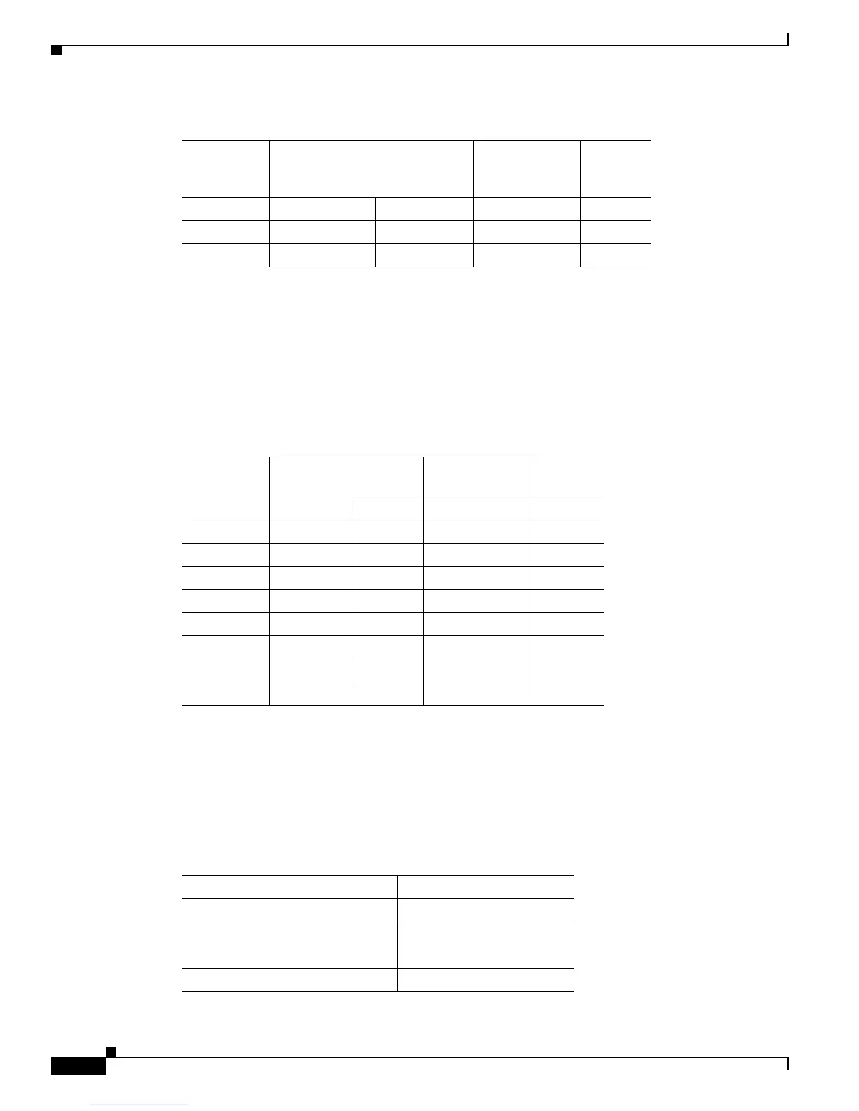
Modem Adapter
Use the RJ-45-to-RJ-45 rollover cable and the RJ-45-to-DB-25 male DCE adapter (labeled “Modem”)
to connect the console port to a modem. Table B-18 lists the pinouts for the asynchronous serial auxiliary
port, the RJ-45-to-RJ-45 rollover cable, and the RJ-45-to-DB-25 male DCE adapter.
Console Port Mode 2 Signaling and Pinouts
This section provides the signaling and pinouts for the console port in mode 2. (The port mode switch
in the out position.) (See Table B-19 for the pinouts.)
DSR 7 3 20 DTR
CTS 8
1
14 RTS
1. Pin 1 is connected internally to Pin 8.
Table B-17 Port Mode 1 Signaling and Pinouts (DB-25 Adapter) (continued)
Console Port RJ-45-to-RJ-45 Rollover Cable
RJ-45-to-DB-25
Terminal
Adapter
Console
Device
Signal RJ-45 Pin RJ-45 Pin DB-25 Pin Signal
Table B-18 Port Mode 1 Signaling and Pinouts
(Modem Adapter)
Console Port
RJ-45-to-RJ-45
Rollover Cable
RJ-45-to-DB-25
Modem Adapter Modem
Signal RJ-45 Pin RJ-45 Pin DB-25 Pin Signal
RTS 1
1
1. Pin 1 is connected internally to Pin 8.
84 RTS
DTR 2 7 20 DTR
TxD 3 6 3 TxD
GND 4 5 7 GND
GND 5 4 7 GND
RxD 6 3 2 RxD
DSR 7 3 8 DCD
CTS 8
1
15 CTS
Table B-19 Port Mode 2 Signaling and Pinouts (Port Mode Switch Out)
Console Port Console Device
Pin (signal) Input/Output
1 (RTS)
1
Output
2 (DTR) Output
3 (RxD) Input