4-57
Catalyst 6500 Series Switches Installation Guide
OL-5781-04
Chapter 4 Removal and Replacement Procedures
Removing and Installing the Fan Assembly
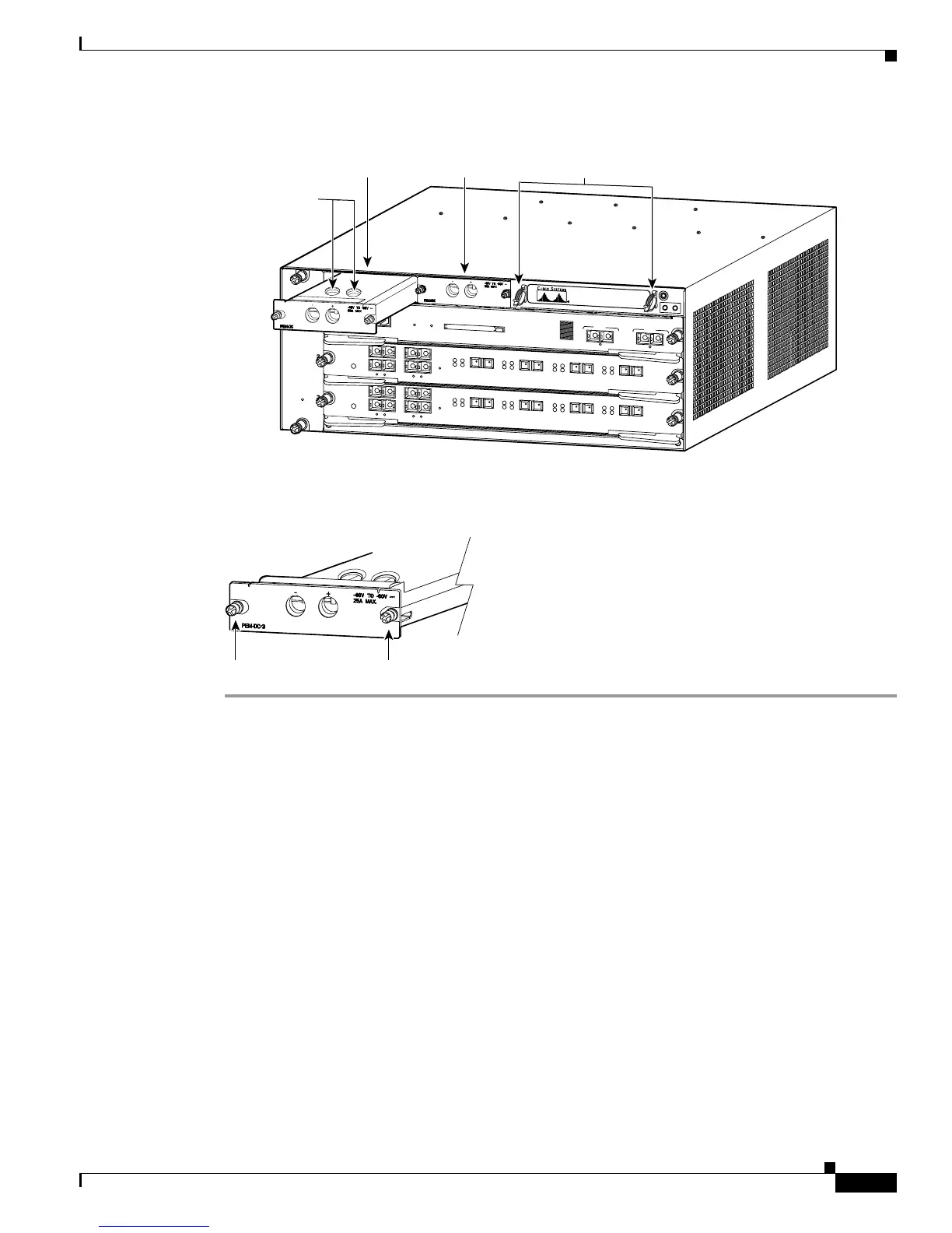
Figure 4-47 DC-Input PEM Terminal Block Screws
Figure 4-48 DC-Input PEM
Removing and Installing the Fan Assembly
This section describes how to remove and install fan assemblies for the Catalyst 6500 series switches.
Required Tools
You might need a flat-blade or number 2 Phillips-head screwdriver to loosen or tighten the captive
installation screws on the power supply.
Removing the Fan Assembly
The fan assembly is designed to be removed and replaced while the system is operating without
presenting an electrical hazard or damage to the system.
S
U
P
E
R
V
IS
O
R
2
W
S
-X
6
K
-S
U
P
2
-2G
E
S
T
A
T
U
S
S
Y
S
T
E
M
C
O
N
S
O
L
E
P
W
R
M
G
M
T
R
E
S
E
T
C
O
NSO
L
E
C
ON
SO
LE
P
O
R
T
M
O
D
E
P
C
M
C
IA EJ
EC
T
P
O
RT
1
P
O
RT
2
Sw
itch Load
100
%
1
%
L
IN
K
L
IN
K
O
S
M
-4
O
C
1
2
P
O
S
-
S
I
4
P
O
R
T
O
C
-1
2
P
O
S
S
M
IR
S
T
A
T
U
S
1
1
2
2
3
3
4
4
R
E
S
E
T
L
I
N
K
L
I
N
K
L
I
N
K
L
I
N
K
C
A
R
R
I
E
R
A
L
A
R
M
C
A
R
R
I
E
R
A
L
A
R
M
C
A
R
R
I
E
R
A
L
A
R
M
C
A
R
R
I
E
R
A
L
A
R
M
A
C
T
I
V
E
T
X
R
X
T
X
P
O
R
T
1
R
X
A
C
T
I
V
E
T
X
R
X
T
X
P
O
R
T
2
R
X
A
C
T
IV
E
T
X
R
X
T
X
P
O
R
T
3
R
X
A
C
T
IV
E
T
X
R
X
T
X
P
O
R
T
4
R
X
O
S
M
-
4
O
C
1
2
P
O
S
-
S
I
4
P
O
R
T
O
C
-1
2
P
O
S
S
M
IR
S
T
A
T
U
S
1
1
2
2
3
3
4
4
R
E
S
E
T
L
I
N
K
L
I
N
K
L
I
N
K
L
I
N
K
C
A
R
R
I
E
R
A
L
A
R
M
C
A
R
R
I
E
R
A
L
A
R
M
C
A
R
R
I
E
R
A
L
A
R
M
C
A
R
R
I
E
R
A
L
A
R
M
A
C
T
I
V
E
T
X
R
X
T
X
P
O
R
T
1
R
X
A
C
T
I
V
E
T
X
R
X
T
X
P
O
R
T
2
R
X
A
C
T
I
V
E
T
X
R
X
T
X
P
O
R
T
3
R
X
A
C
T
I
V
E
T
X
R
X
T
X
P
O
R
T
4
R
X
68154
DC PEM 1
Cable clips
DC PEM 1
terminal block
screws
DC PEM 2
Captive installation screws
Catalyst 6503 DC PEM
79980