4-51
Catalyst 6500 Series Switches Installation Guide
OL-5781-04
Chapter 4 Removal and Replacement Procedures
Removing and Installing the Power Entry Modules (PEMs)
Step 16 Turn the power switch to the On (|) position on the power supply. Turning on the power switch also
engages a pawl that locks the power supply in the chassis.
Step 17 Verify the power supply operation by ensuring that the power supply front panel LEDs are in the
following states:
• INPUT OK LED is green
• FAN OK LED is green
• OUTPUT FAIL LED is not lit
If the LEDs indicate a power problem, see the “Identifying Startup Problems” section on page E-3.
Removing and Installing the Power Entry Modules (PEMs)
This section describes how to remove and install the PEMs for the Catalyst 6503 and Catalyst 6503-E
switches. There are three PEM models:
950 W AC-input PEM—PEM-15A-AC
1400 W AC-input PEM—PEM-20A-AC+
950 W DC-input PEM—PEM-DC/3
Note The PEM is used on the Catalyst 6503 and Catalyst 6503-E switches only.
The PEM provides an input power connection on the front of the chassis to connect the site power source
to the power supply. In addition to providing an input power connection, the PEM also has an illuminated
power switch (AC-input only), current protection, surge and EMI suppression, and filtering functions.
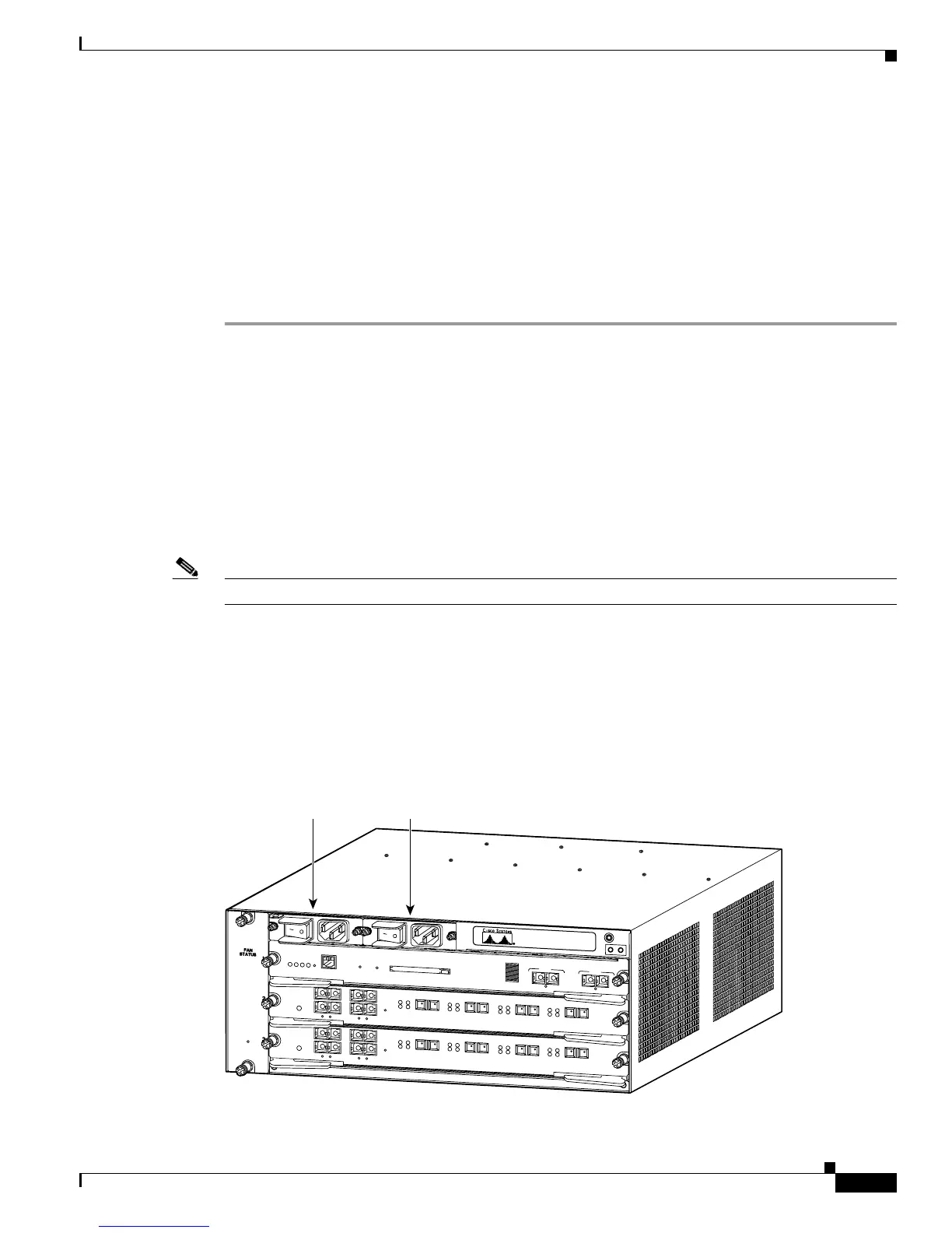
See Figure 4-40 for the location of the PEM; see Figure 4-41 for the location of the power supplies. The
PEM on the left (PEM 1) connects the site power source to power supply 1; the PEM on the right (PEM
2) connects the site power source to power supply 2.
Figure 4-40 Catalyst 6503—PEM Location
S
U
P
E
R
V
IS
O
R
2
W
S
-X
6
K
-S
U
P
2
-2
G
E
S
T
A
T
U
S
S
Y
S
T
E
M
C
O
N
S
O
L
E
P
W
R
M
G
M
T
R
E
S
E
T
C
O
N
S
O
LE
C
O
N
S
O
LE
P
O
R
T
M
O
D
E
P
C
M
C
IA E
JE
C
T
P
O
R
T
1
PO
R
T
2
S
w
itch Load
100%
1%
L
IN
K
L
IN
K
O
S
M
-4
O
C
1
2
P
O
S
-S
I
4
P
O
R
T
O
C
-
1
2
P
O
S
S
M
IR
S
T
A
T
U
S
1
1
2
2
3
3
4
4
R
E
S
E
T
L
I
N
K
L
I
N
K
L
I
N
K
L
I
N
K
C
A
R
R
I
E
R
A
L
A
R
M
C
A
R
R
I
E
R
A
L
A
R
M
C
A
R
R
I
E
R
A
L
A
R
M
C
A
R
R
I
E
R
A
L
A
R
M
A
C
T
I
V
E
T
X
R
X
T
X
P
O
R
T
1
R
X
A
C
T
I
V
E
T
X
R
X
T
X
P
O
R
T
2
R
X
A
C
T
I
V
E
T
X
R
X
T
X
P
O
R
T
3
R
X
A
C
T
I
V
E
T
X
R
X
T
X
P
O
R
T
4
R
X
O
S
M
-
4
O
C
1
2
P
O
S
-S
I
4
P
O
R
T
O
C
-
1
2
P
O
S
S
M
IR
S
T
A
T
U
S
1
1
2
2
3
3
4
4
R
E
S
E
T
L
I
N
K
L
I
N
K
L
I
N
K
L
I
N
K
C
A
R
R
I
E
R
A
L
A
R
M
C
A
R
R
I
E
R
A
L
A
R
M
C
A
R
R
I
E
R
A
L
A
R
M
C
A
R
R
I
E
R
A
L
A
R
M
A
C
T
IV
E
T
X
R
X
T
X
P
O
R
T
1
R
X
A
C
T
I
V
E
T
X
R
X
T
X
P
O
R
T
2
R
X
A
C
T
I
V
E
T
X
R
X
T
X
P
O
R
T
3
R
X
A
C
T
I
V
E
T
X
R
X
T
X
P
O
R
T
4
R
X
63191
PEM 1 PEM 2