4-52
Catalyst 6500 Series Switches Installation Guide
OL-5781-04
Chapter 4 Removal and Replacement Procedures
Removing and Installing the Power Entry Modules (PEMs)
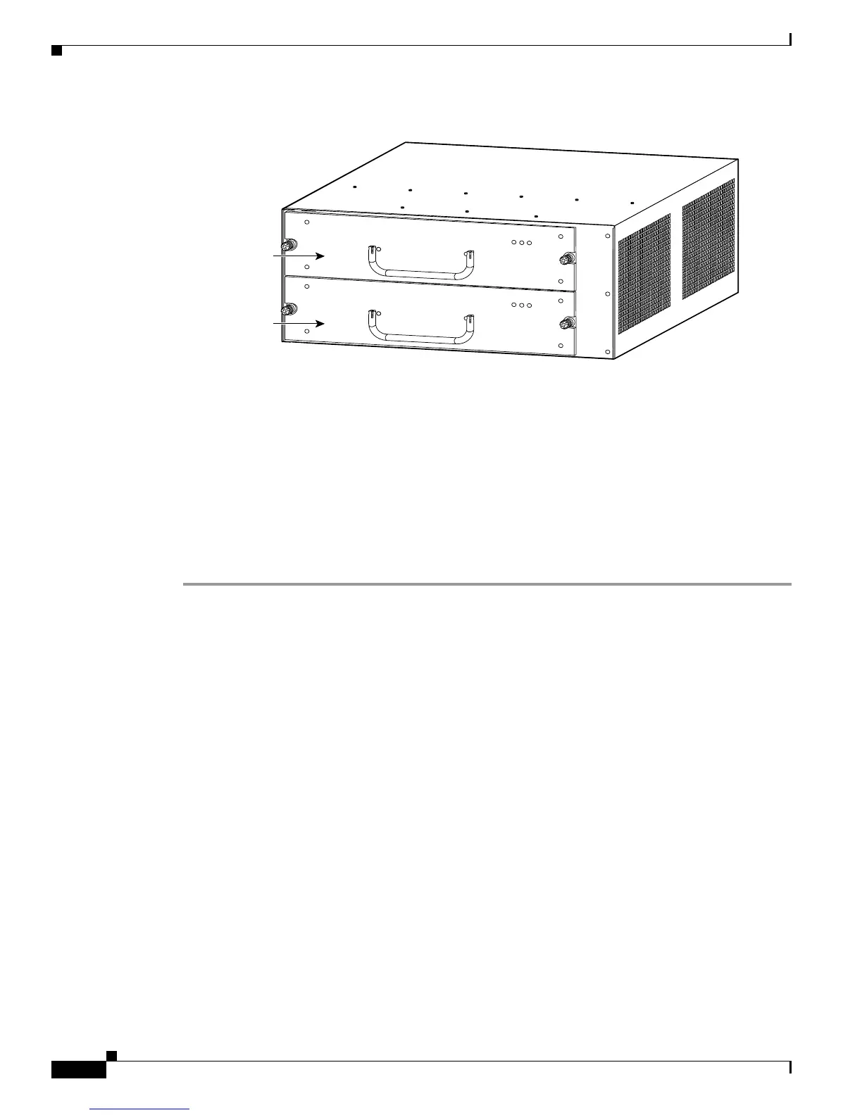
Figure 4-41 Catalyst 6503 Switch—Power Supply Location
Required Tools
Use a flat-blade or number 2 Phillips-head screwdriver to perform these procedures. Additionally, wire
cutters may be necessary to cut cable tie-wraps.
Removing the AC-Input PEM
Follow these steps to remove an AC-input PEM:
Step 1 Turn the power switch to the Off (0) position on the PEM that you are removing. (See Figure 4-40.)
Step 2 Disconnect the power cord from the power source. Do not touch the metal prongs on the power cord
when it is still connected to the PEM.
Step 3 Remove the power cord from the power connection on the PEM. Do not touch the metal prongs
embedded in the PEM.
Step 4 Loosen the captive installation screws. (See Figure 4-42.)
Step 5 Grasp the PEM with one hand, and slide it part of the way out of the chassis. Place your other hand
underneath the PEM, as shown in Figure 4-43, and slide it completely out of the chassis.
Step 6 If the PEM bay is to remain empty, install a blank PEM filler plate (Cisco part number 800-16719-01)
over the opening, and secure it with the captive installation screws.
63031
INPUT
OK
FAN
OK
OUTPUT
FAI L
INPUT
OK
FAN
OK
OUTPUT
FAI L
Power supply 2
(redundant)
Power supply 1