B-25
Catalyst 6500 Series Switches Installation Guide
OL-5781-04
Appendix B Transceivers, Module Connectors, and Cable Specifications
Cables
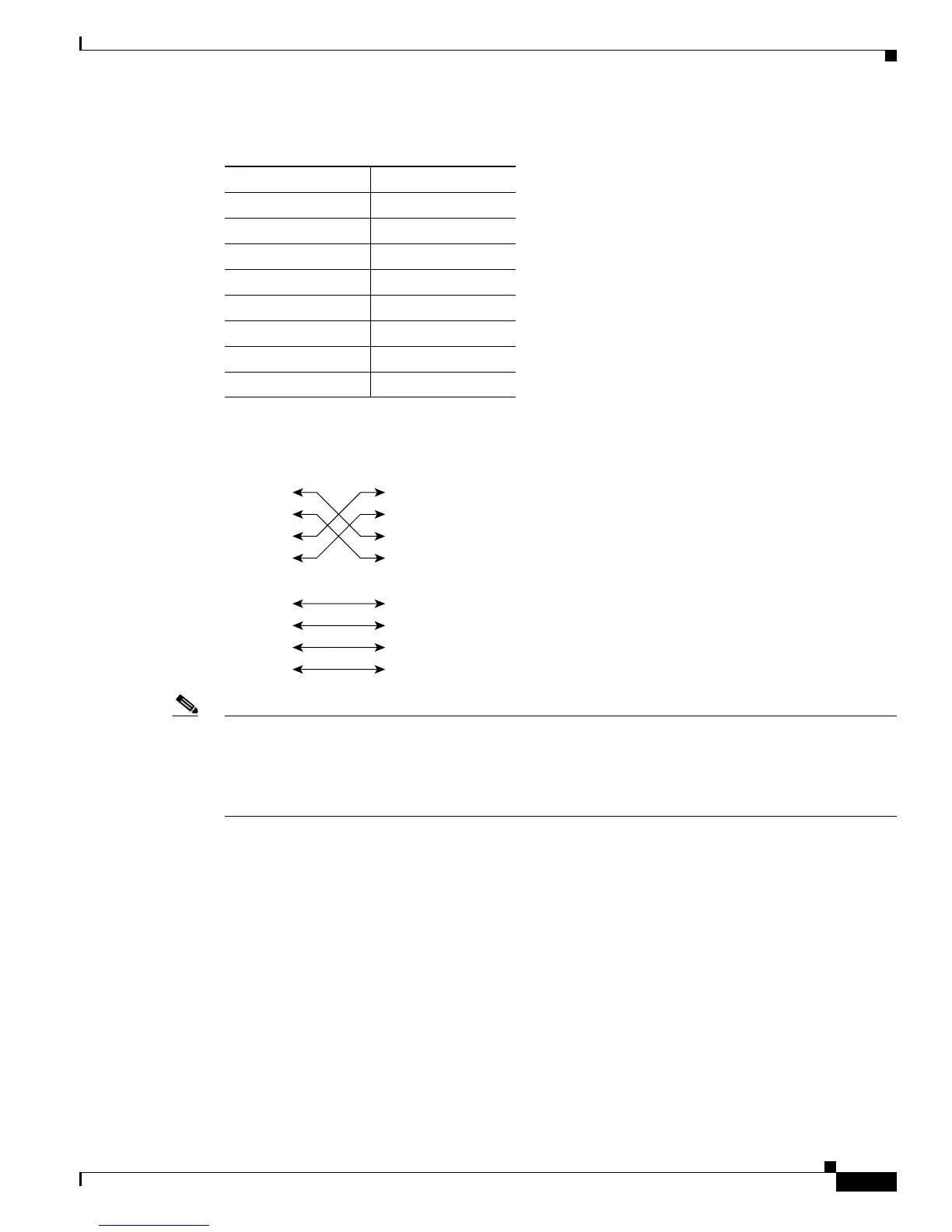
Figure B-17 Twisted-Pair Crossover 1000BASE-T Cable Schematic
Note Power over Ethernet (PoE), uses pairs 2 and 3 (pins 1, 2, 3, and 6) in a four-pair UTP cable to transmit
power from the switch to a powered device. This method of supplying power is sometimes called
“phantom power” because the PoE power travels over the same pairs of wires used to transmit the
Ethernet signals. The PoE voltage is completely transparent to the Ethernet signals and does not interfere
with their operation.
Catalyst 6500 series switches come with an accessory kit that contains the cable and adapters that you
will need to connect a console (an ASCII terminal or PC running terminal emulation software) or modem
to the console port. The accessory kit includes these items:
• RJ-45-to-RJ-45 rollover cable
• RJ-45-to-DB-9 female DTE adapter (labeled “Terminal”)
• RJ-45-to-DB-25 female DTE adapter (labeled “Terminal”)
• RJ-45-to-DB-25 male DCE adapter (labeled “Modem”)
Table B-15 1000BASE-T Crossover Cable Pinout (MDI-X)
Side 1 Pin (Signal) Side 2 Pin (Signal)
1 (TP0+) 3 (TP1+)
2 (TP0–) 6 (TP1–)
3 (TP1+) 1 (TP0+)
6 (TP1–) 2 (TP1–)
4 (TP2+) 7 (TP3+)
5 (TP2–) 8 (TP3–)
7 (TP3+) 4 (TP2+)
8 (TP3–) 5 (TP2–)
1 TPO+
2 TPO-
3 TP1+
6 TP1-
1 TP0+
Switch Switch
2 TP0-
3 TP1+
6 TP1-
4 TP2+
5 TP2-
7 TP3+
8 TP3-
4 TP2+
5 TP2-
7 TP3+
8 TP3-
65274